1
097-55501-01 Issue 6 – June 2003 111
2
5
3
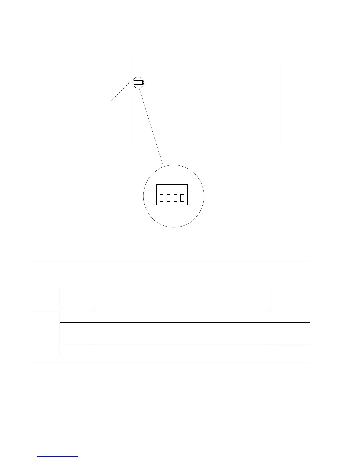
Operational Verification & Configuration
Figure 4-9. Clock Card Switch S1
Table 4-3. S1 Switch Settings
S1
Section
Position Description Factory
Setting
1 On Normal operation X
Off Mixed oscillator operation. This card contains a secondary
oscillator
–
2-4 On Not used X
4
Note: Switch S1 is shown in the factory-set position.
Front Panel
S1
2
3
(On)
1

 Loading...

