1
097-55501-01 Issue 6 – June 2003 93
2
5
3
Installation
DS1 Monitor
Connect the DS1 monitor inputs to the remaining DS1 Reference pins, or to
the wirewrap pins labeled DS1 MON on the Input/Alarm Connector module
(Figure ). Nine-input clock cards (090-55512-02 or 090-55514-02) are
required if the DS1 MON pins are used. Connect the tip wire to the pins
labeled T, the ring wire to the pins labeled R, and the shield (if connected at
the TimeHub 5500) to the pins labeled S.
PRS Input
Connect the PRS input to the BNC connector labeled 5/10 MHz IN on the
Input/Alarm Connector module. See Figures and for the connector location.
3.8.3.4 Communication Ports
LAN
Connect the LAN cable from the network to the RJ-45 (10Base-T) connector
labeled LAN on the rear of the shelf. Refer to Figure 3-11 for the connector
location, and Table 3-3 for the connector pinouts.
Local
To provide an RS-232 link for TL1 command access to the TimeHub 5500,
connect to the data terminal equipment (DTE) equivalent communication
port 1 at the nine-pin connector labeled Local on the rear of the shelf. See
N
OTE
: Each TimeHub 5500 will have its own IP address that
can be set through the local RS-232 port. Once the IP address
has been set and a LAN connection made, the TimeHub 5500
can be remotely accessed on a network.
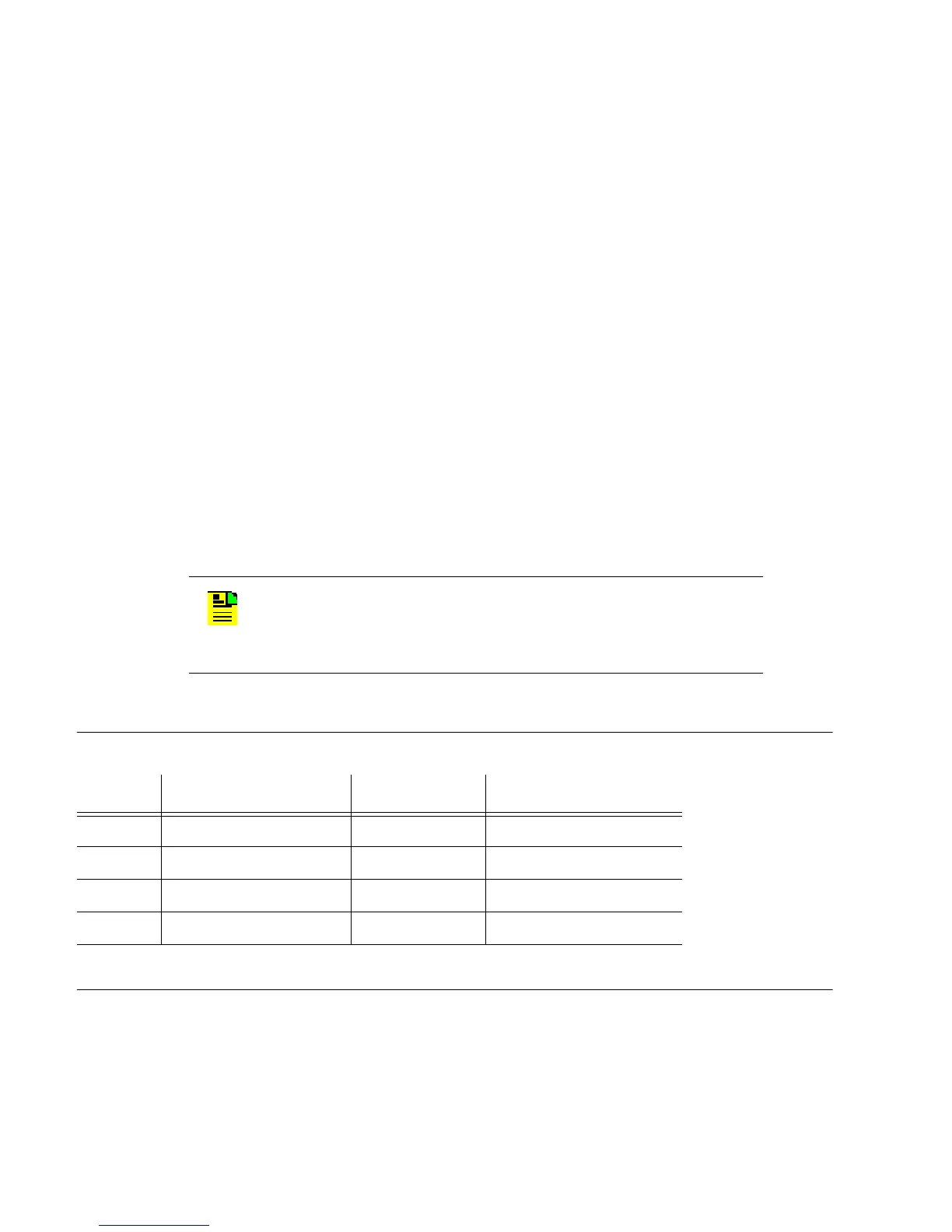
Table 3-3. LAN Pinouts
Pin Signal Abbreviation Direction
1 Transmit data + TXD + From TimeHub 5500
2 Transmit data – TXD – From TimeHub 5500
3 Receive data + RXD + To TimeHub 5500
6 Receive data – RXD – To TimeHub 5500
Note: Pins not listed are reserved for future use.

 Loading...

