Forward Error Correction in IP Networks 175
ID: um_t2gateway CP560 DVB-T2 Gateway User’s Manual Rev. 2.2 (3686)
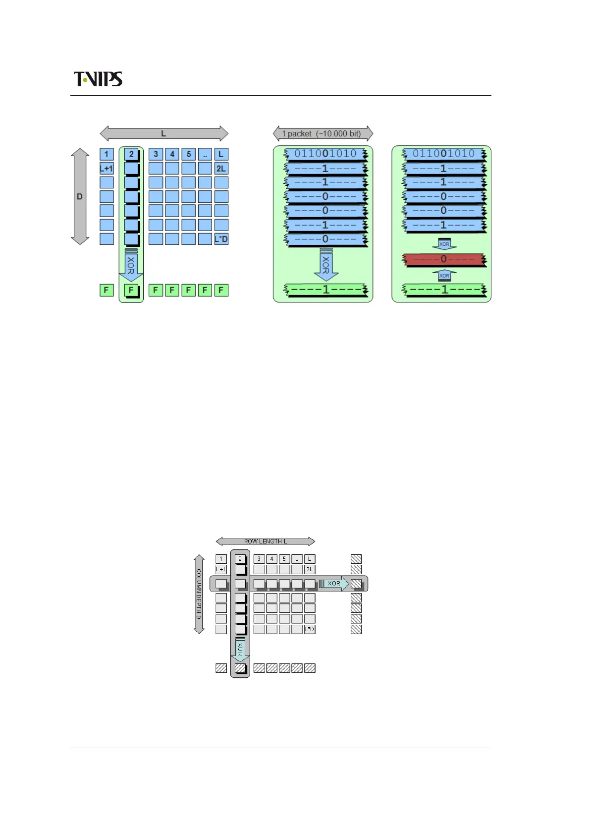
Figure C.2 IP packet FEC calculation matrix
Figure C.2 shows LxD consecutive IP packets arranged in a matrix. The FEC checksum is
calculated over the columns, which means that the distance between two packets used in an
XOR calculation is L. An XOR sum is calculated for each bit position of all the packets of a
column. The checksums for all bit positions constitute the FEC checksum, and is inserted in
a FEC packet which is sent in addition to the payload packets. There will be one FEC packet
associated with each column, and it is therefore possible to regenerate as many packets as there
are columns in the matrix.
In the right-most panel of Figure C.2 the case is shown where a packet in the last column
position has been lost. The packet may then be regenerated (shown in red) by performing XOR
addition over all remaining packets in that column, including the FEC packet. This is the default
FEC mode of SMPTE 2022-1.
However, it is not possible to correct more than one error in a column. To increase the error
correction capability the specification gives the option to also include FEC over the rows. By
combining the two FEC calculations it is now possible to handle more complex packet loss
distribution patterns and correct up to L+D lost packets.
Figure C.3 Two-dimensional FEC calcula-
tion matrix