RUN MED: Service & Maintenance Manual - rev. 1.0
8.5. POSITION OF THE LIMIT SWITCH
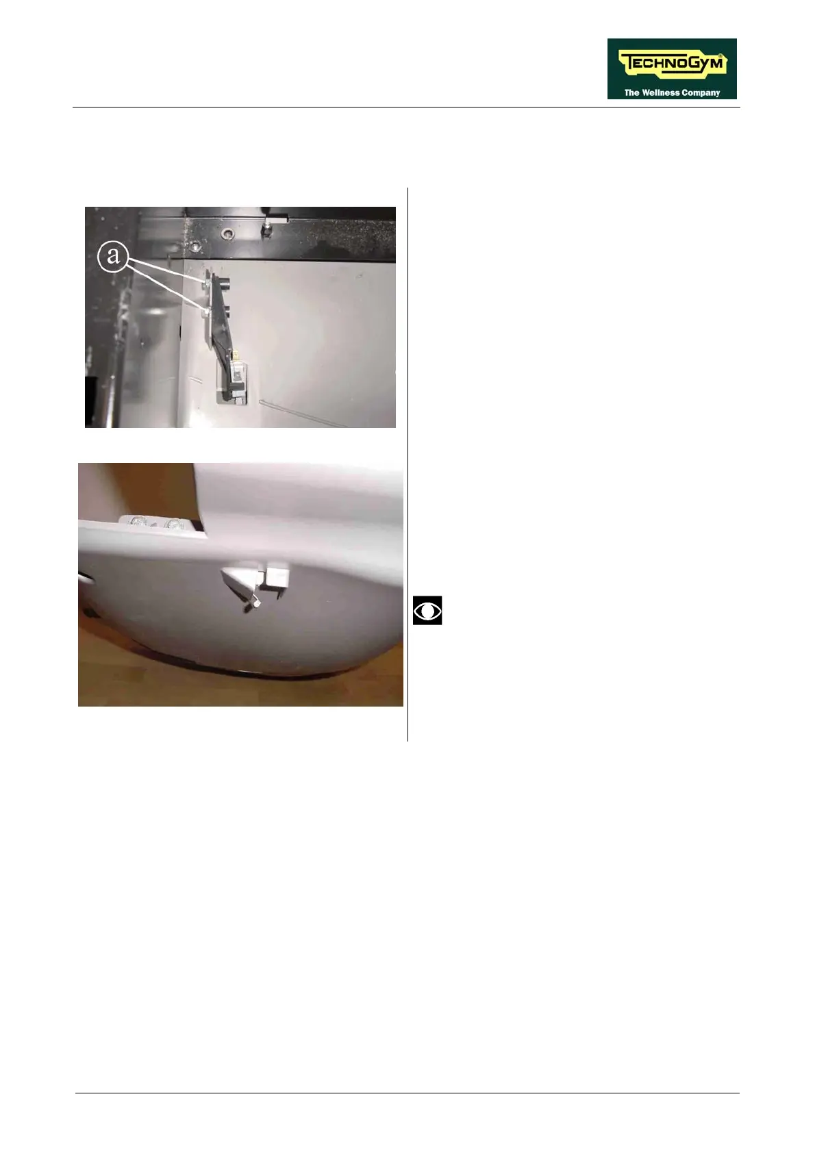
Figure 8.5-1
Carry out the procedure described in paragraph
7.9. “Disassembling the motor guard”, only as
far as removing the upper guard and 7.11.
“Disassembling the electrical box”.
1. Back off the 2 screws a fixing the limit
switch.
Figure 8.5-2
2.
at the lever which trips it
touches the guard in the microswitch
com
Adjust the position of the microswitch
support so th
partment.
Under no circumstances should the lever
3. After making the adjustment, lock down the
screws a backed off previously.
be pressed by the guard.
Page 8.5