RUN MED: Service & Maintenance Manual - rev. 1.0
Do the pulses correctly reach
the AT driv er board input?
YES
NO
Replace the encoder
4
A
Replace AT driv er
board
Is the 400VAC v oltage
correctly supplied by the AT
driv er board?
YES
Replace the power
supply board
3
NO
Replace the AT driver
board
B
Follow the procedure step by step to correctly diagnose the problem. Take particular care with the
checks highlighted by circled numbers, which are described in detail below:
(1) Place the tester probes across pins 3 and 1 of the connector J6 on the AT driver board. The
measured voltage should be 5 Vdc.
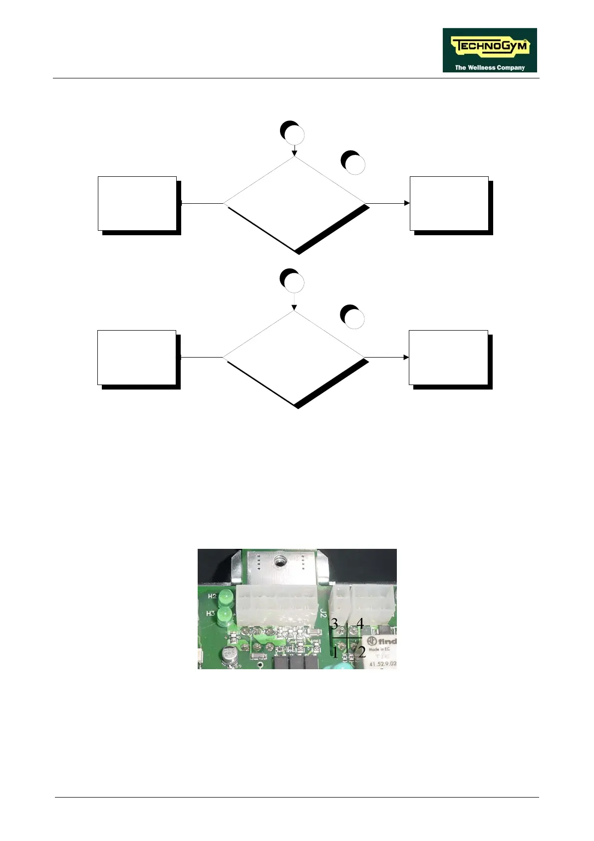
(2) Using a tester, check the voltages on the back of connector XU1 on the AT drive board,
placing the probes on test points 3-4 to measure the 5 Vdc signal (see figure below).
(3) Check that the red LED H5, on the AT driver board is on.
(4) Place the tester probes across pins 2 and 4 of the connector J6 on the AT driver board. The
measured value should be approximately 300-400 mV when the motor is running. If an
oscilloscope is available, it is possible to view the pulses produced by the encoder itself.
Page 6.25