RUN MED: Service & Maintenance Manual - rev. 1.0
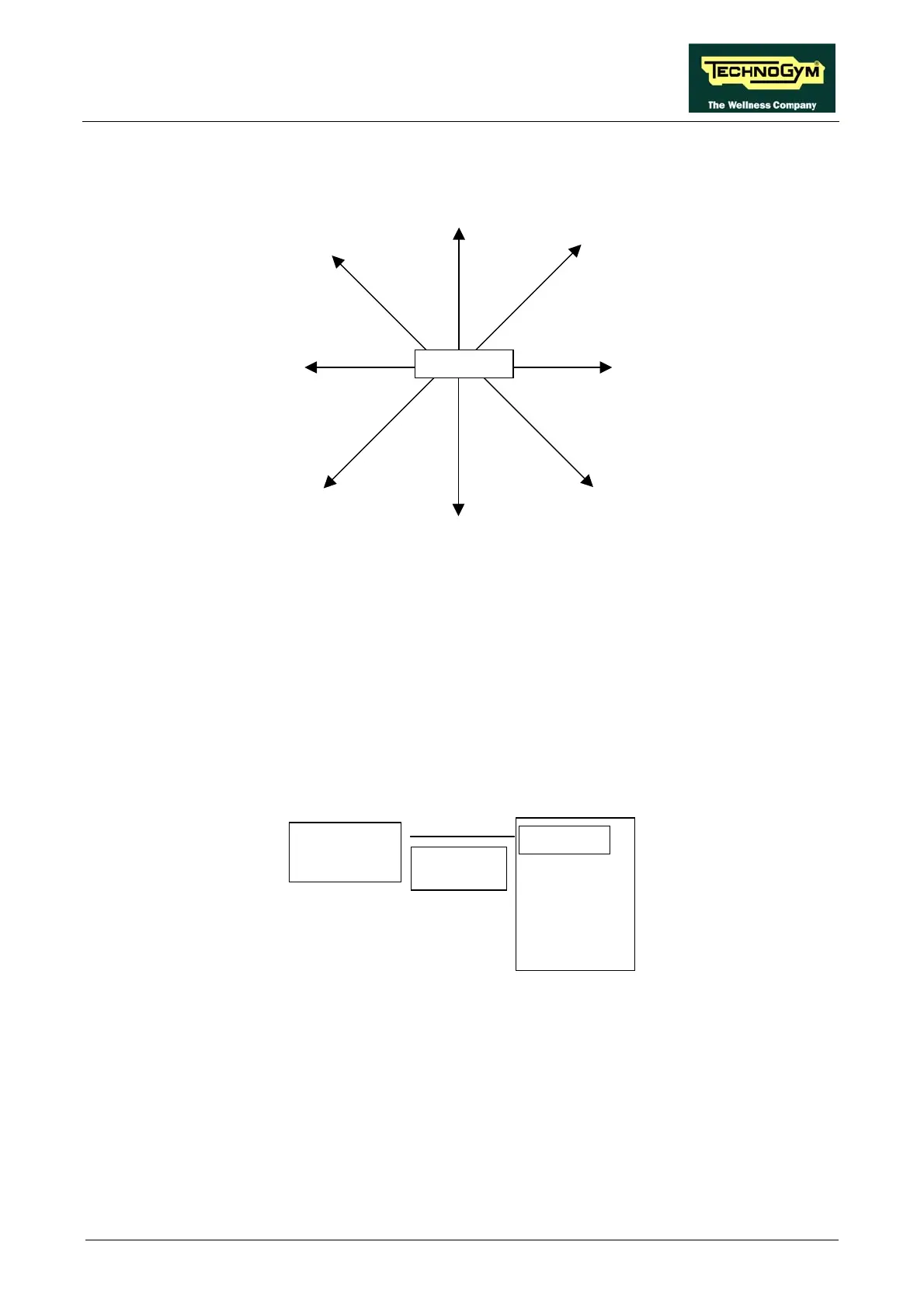
For machine positioning layouts different from those indicated above, use the following
diagram as a reference.
115
86
102
70
103
83
103
82
95
76
99
78
89
60
99
77
Receiver
where:
1. The distances are in centimeters.
2. The smaller number indicates the maximum locking distance for signal reception at the
start of the exercise.
3. The higher number indicates the maximum reception distance during the exercise.
(3) Check that the cardio receiver has been assembled properly as described in the procedure 7.7.
“Disassembling the cardio receiver”.
(4) To check for electromagnetic noise near the machine, use Test Box Excite as detailed here
below. You can use one of the following cables ELT-16 (0WC00518AB), CBQ-28
(0WC00390AC) or TRM-28 (0WC00336AC) as connection cable.
HFU
The circuit lights the LED for each heart beat and/or disturbance received: in this way it is
possible to determine whether there is any interference, and identify its sources.
(5) Check the battery power level, using a tester if possible. Otherwise use a receiver or another
“reference” machine to check the operation up to a distance of about 80 cm from the receiver.
Receiver
TEST BOX
EXCITE
HR receive
Connect
cable
ion
Page 6.39