D292144.4.fm Preparing the Work Area
Chapter 1: Assembly & Installation 1- 3
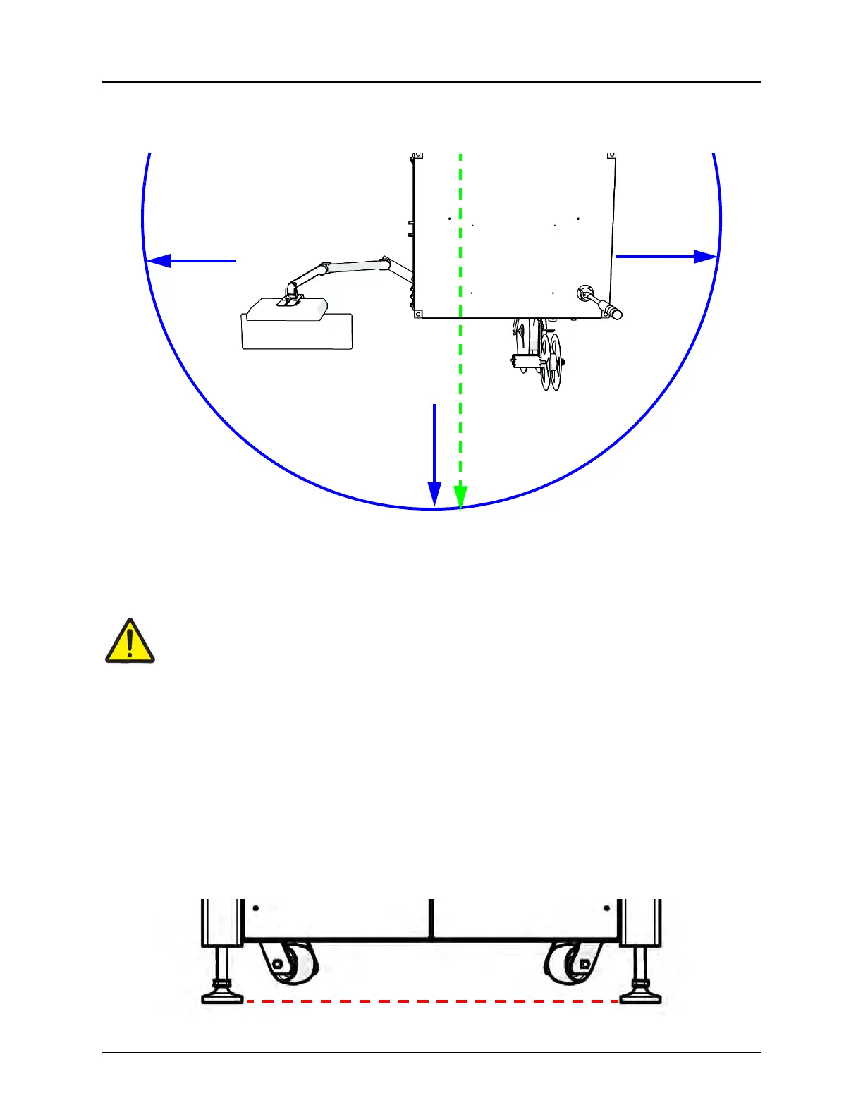
Allow at least three feet of clearance at the front and sides of the machine for easy access and
operation. A birds-eye view of the TM-500 with minimum clearance on front and sides is shown
below.
When positioning the TM-500, choose an area that is not located below overhead gantries, walk-
ways or power lines to ensure objects or liquids cannot be dropped on the machine from over-
head.
Caution!
Operators should use caution when working in front of the TM-500. Be aware of Takeup
Arm and Carrier Arm positions to avoid tripping.
Power Requirements
The TM-500 will also require access to a 85-110 PSI air pressure system and a 230/240 VAC,
50-60 Hz power supply. Locate the machine so electrical power cables can be routed away from
areas where personnel are expected to move.
Note: It is recommended that cables be routed overhead or underground. If cables must
be routed over the floor, cover them with rubber ramps.
Stabilizing the TM-500
Ensure that the four TM-500 feet are extended beyond the wheels so the machine is immobilized
and level during operation.
Minimum clearance =
3’ on front & sides
Minimum Work
Space Depth
9 feet