D292144.4.fm Assembling the TM-500
Chapter 1: Assembly & Installation 1- 5
Assembling the TM-500
Caution: Users should always wear protective eye wear when operating or
maintaining the TM-500.
Equipment Required
Adjustable wrench (needs to fit 1 1/16” to 1 3/32” nut)
Hex wrench set (provided with machine)
85-110 PSI air pressure system
Note: Read the TM-500 User’s Guide before assembling the TM-500.
1. Unpack the Crate.
a. Remove the smaller items one at a time from the crate and place on a flat, stable sur-
face for assembly.
b. Remove and discard the protective wrapping from each part.
2. Remove the TM-500 from the Crate.
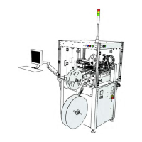
a. Unfasten the two straps that anchor
the base machine to the crate
The base machine weighs approximately
1,200 pounds (545 kg) and is mounted
with four wheels and four stationary legs.
During shipment, the legs are extended
and locked in place to prevent movement
within the crate.
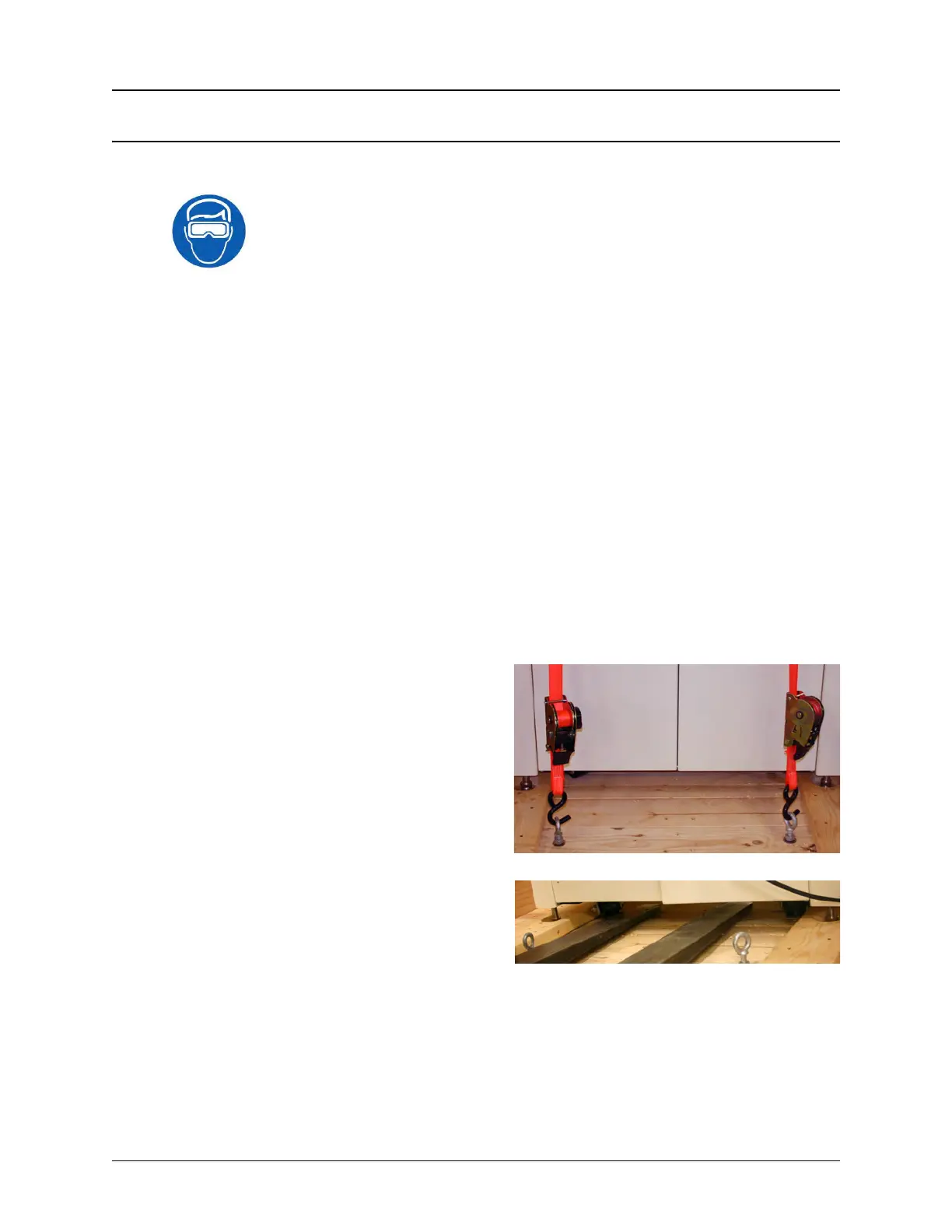
b. Use a forklift to lift the TM-500 out of
the crate. Ensure the fork is positioned
between both sets of legs and centered
under the machine before lifting.
Note: Use a forklift with a minimum load capacity of 1,200 pounds (545 kg) and a fork
length that is a minimum of 50 inches (130cm) so the fork fully extends beyond the base
machine on the other side. The forklift should only be operated by a licensed/certified
operator.