1-6 TM-500 User’s Guide
Assembling the TM-500 D292144.4.fm
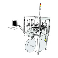
3. Moving the TM-500 to the Work Area.
a. Using an adjustable wrench, gradually raise
the TM-500 legs, rotating around the machine
until all four legs are raised above the wheels
and the machine rests on its wheels.
b. Position two people at opposite corners of
the machine to guide it and roll the TM-500
from the crate to the prepared work area for
assembly.
Caution!
The TM-500 should only be rolled along a flat, level surface. Do not attempt to roll it
up or down a ramp.
c. Position the TM-500 in the work area so there is at least 3 feet of clearance on the
front. left and right sides. (See the Preparing the Work Area section earlier in this chapter
for details.)
d. Using the adjustable wrench, lower the TM-500 legs until they are extended below the
plane of the wheels so the wheels are once again immobilized. Use a level to adjust the
legs so the machine is stable and level.
e. The TM-500 is shipped with twist ties securing the pick head and any mobile portions
of the machine. If the optional Tray Input Module or 2D Vision System were purchased,
they will also be secured with zip-ties. Cut and remove all twist ties.
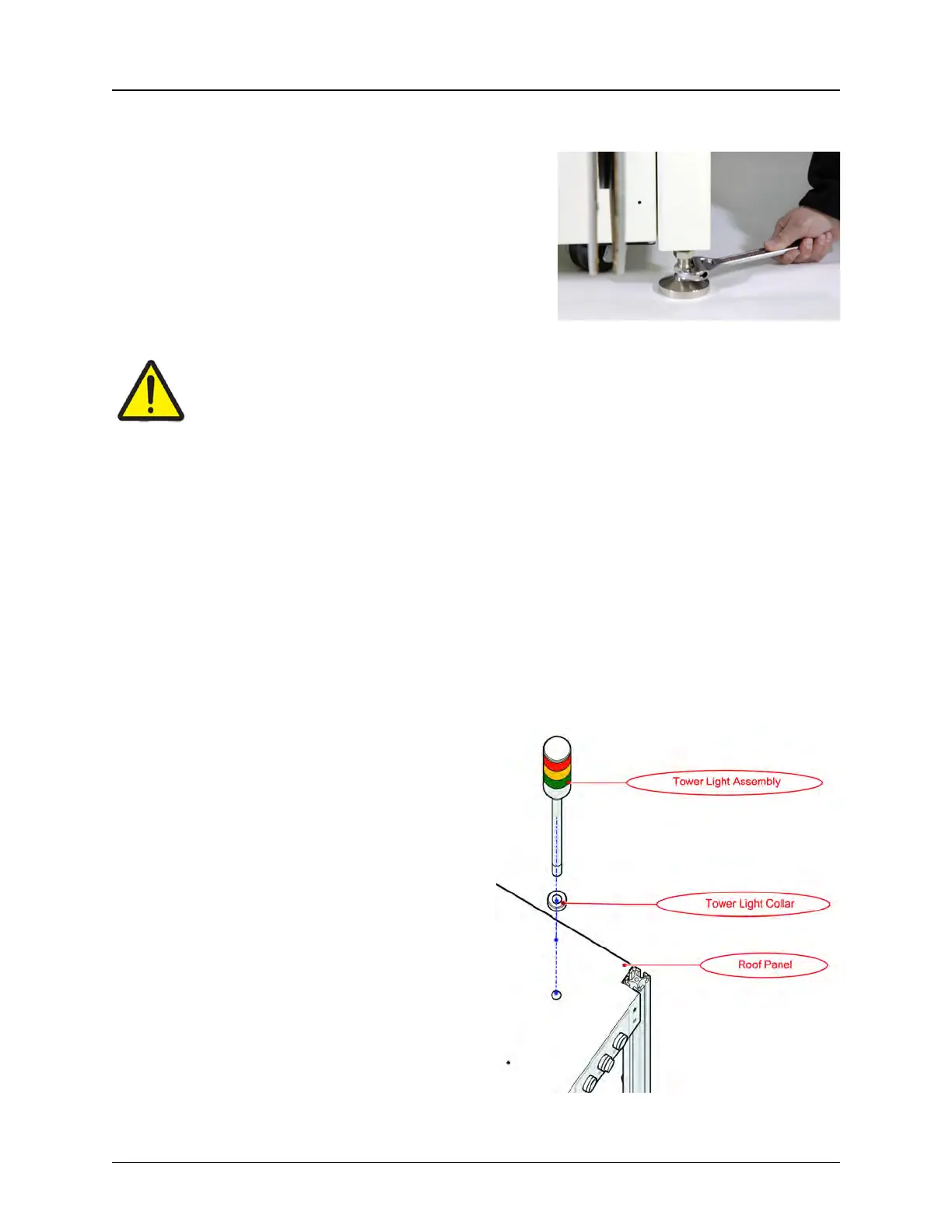
4. Connect the Tower Light
a. Remove the front Wire Cover from
the inside of the roof enclosure.
b. Position a ladder securely next to the
front of the TM-500.
c. There are two bolts on the bottom of
the Tower Light. Unscrew the bottom one
and set it aside.
d. Thread the Tower Light wires and the
bottom of the Tower Light through the
hole in the top front corner on the top of
the enclosure.