D292144.4.fm Assembling the TM-500
Chapter 1: Assembly & Installation 1- 7
e. Replace the bottom bolt on the inside of the enclosure so the enclosure roof is sand-
wiched between the two bolts. Tighten the bolts until the Tower Light is secure.
f. Plug the Tower Light wire 4 Pin Molex Connector into the matching receptacle inside
the enclosure.
g. Replace the front wire cover.
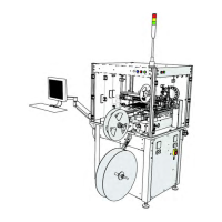
5. Connecting the Carrier Tape Arm & Low Carrier
Tape Sensor
a. Use an 4 mm hex wrench to connect the Car-
rier Tape Spindle to the Carrier Tape Arm.
b. Use an 8 mm hex wrench to connect the Car-
rier Tape Arm to the front right corner of the
machine.
c. Open the lower front enclosure and locate the
Low Carrier Tape Sensor wire. Cut the zip tie hold-
ing it in place and thread the wire through the
space between the upper and lower enclosures
near the Carrier Tape Arm.
d. Use an 3/32” hex wrench to connect the Low
Carrier Sensor to the Carrier Tape Arm, then con-
nect the sensor wire to the sensor. Pivot the sen-
sor in the slot to the desired position. (This will vary
with reel and tape size.)
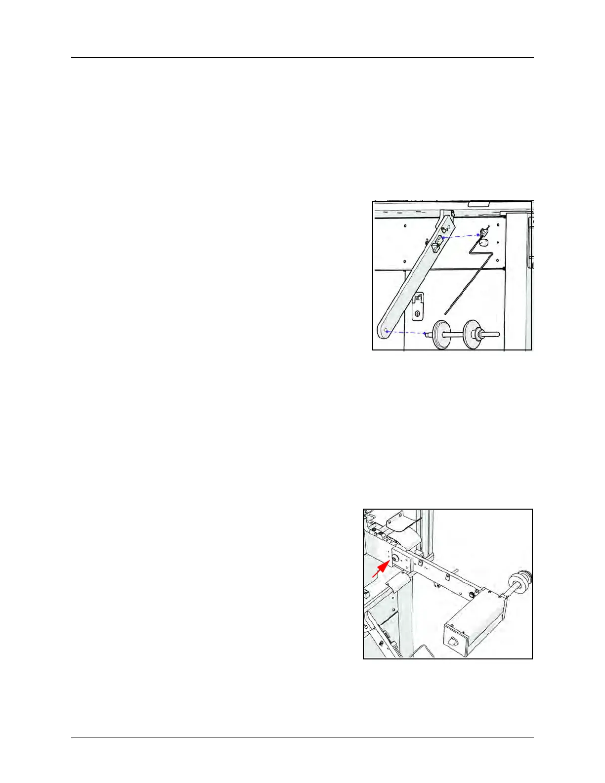
6. Connecting the Take-up Arm
a. Use an 1/4” hex wrench to connect the Take-
up Arm.
b. Plug the power cord into the power recepta-
cle on the front of the machine.