3-42 Engine Electrical Industrial 1.6L
Voltage Regulator
The integral voltage regulator protects the unit’s
operating accessories from receiving high voltage and
the battery from being overcharged. No current
regulation is needed because it determined by the
design of the generator.
The regulator is an extremely reliable device composed
of two circuits. One of these circuits is used to sense
voltage and control the other circuit which cycles the
field current “on and off” to prevent voltage from going
to high.
The regulator limits system voltage by controlling the
rotor field current. When the field current is on, the
regulator switches the rotor field on and off at a fixed
rate of about 400 cycles per second. By varying the
overall on/off time, correct average field current for
proper system voltage control is maintained. At high
speeds, the on time may be 10 percent and the off time
may be 90 percent. At low speeds, and with high
electrical loads, the on/off time may be 90 percent and
10 percent respectively.
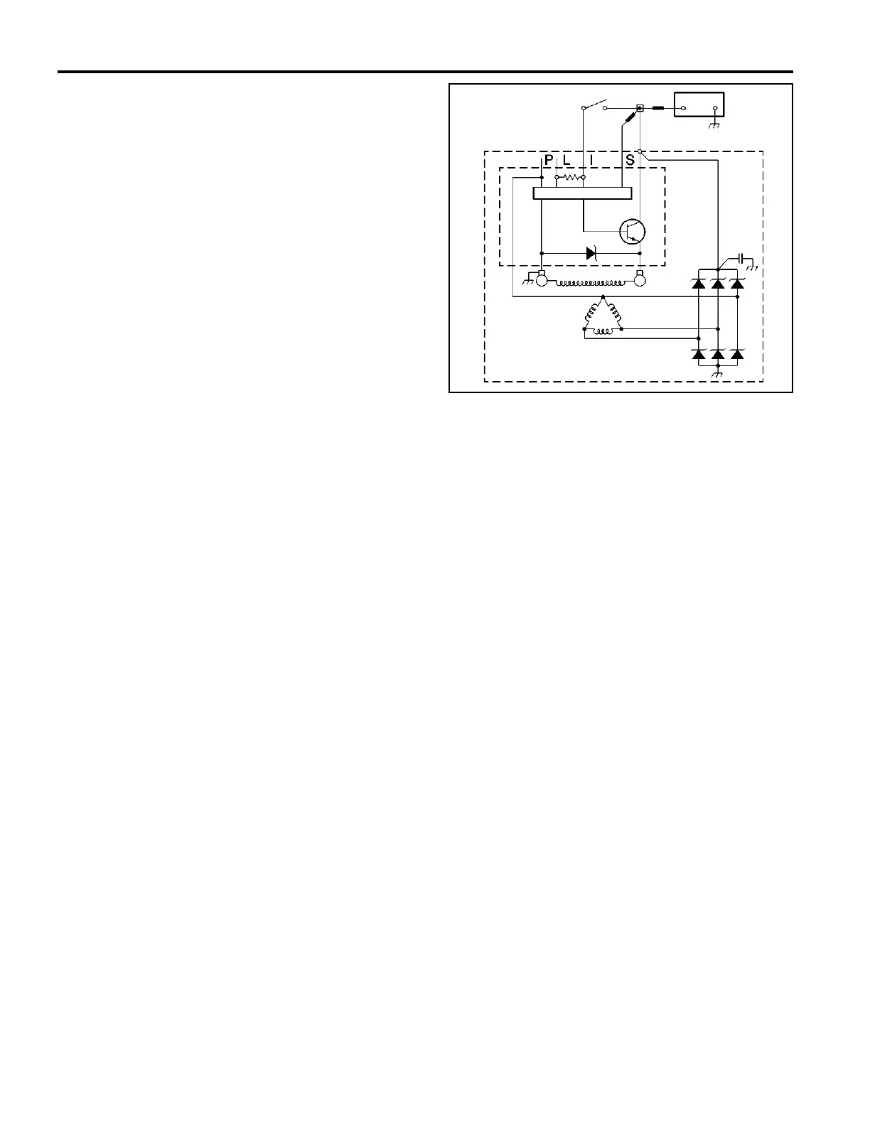
The regulator has four terminals, The terminals are P,
L, I, and S. These letters are stamped on the regulator.
Generally, in SI generators the S terminal senses the
state of the battery and allows field current flow when
the switch is closed.
When the battery voltage rises to predetermined level,
the sensing circuit tells the regulator to turn OFF. This
decreases the magnetic field around the field coil and
generator voltage is limited to a safe value.
When the battery voltage drops below a predetermined
level, the sensing circuit tells the regulator to turn ON.
This increases the magnetic field around the field coil
and generator voltage begins to charge the battery.
Charging System Circuit Description
The generator provides voltage that operates the
electrical system of the vehicle and that also charges
the battery and the secondary battery. A magnetic field
is created when current flows through the rotor. The
field rotates as the rotor is driven by the engine,
creating an AC voltage in the stator windings. The
rectifier bridge converts the AC voltage to DC and this
goes to the electrical system at the terminal to the
battery.
The digital regulator of the generator uses digital
techniques in order to supply the rotor current. Be-
cause of this, the digital regulator controls the output
voltage. The rotor current is proportional the width of
the electrical pulses supplied from the electrical system
through the RED wire connected between the battery
and S terminals on the generator .
When the ignition switch is turned to the RUN position,
current from the battery flows through the closed
contacts of the switch, to the voltmeter gauge on the
instrument panel, the voltage regulator, and through the
field coil of the generator rotor.
With current applied to the digital regulator, the regula-
tor turns on. Narrow width pulses go to the digital rotor
circuit, creating a weak magnetic field. When the
engine starts, the digital regulator senses the rotation
of the generator by detecting AC voltage at the stator
through an internal wire. Once the engine is running,
the digital regulator varies the field current by control-
ling the pulse width. This regulates the output voltage of
the generator for proper charging of the battery and
operation of the electrical system.
375662