Industrial 1.6L Engine Electrical 3-39
Description and Operation
Starting System Description
Cranking Circuit
The cranking circuit consists of the following compo-
nents:
• The battery
• The starter motor
• The ignition switch
• All related electrical wiring
For detailed schematics of the starting system refer to
Schematic and Routing Diagrams.
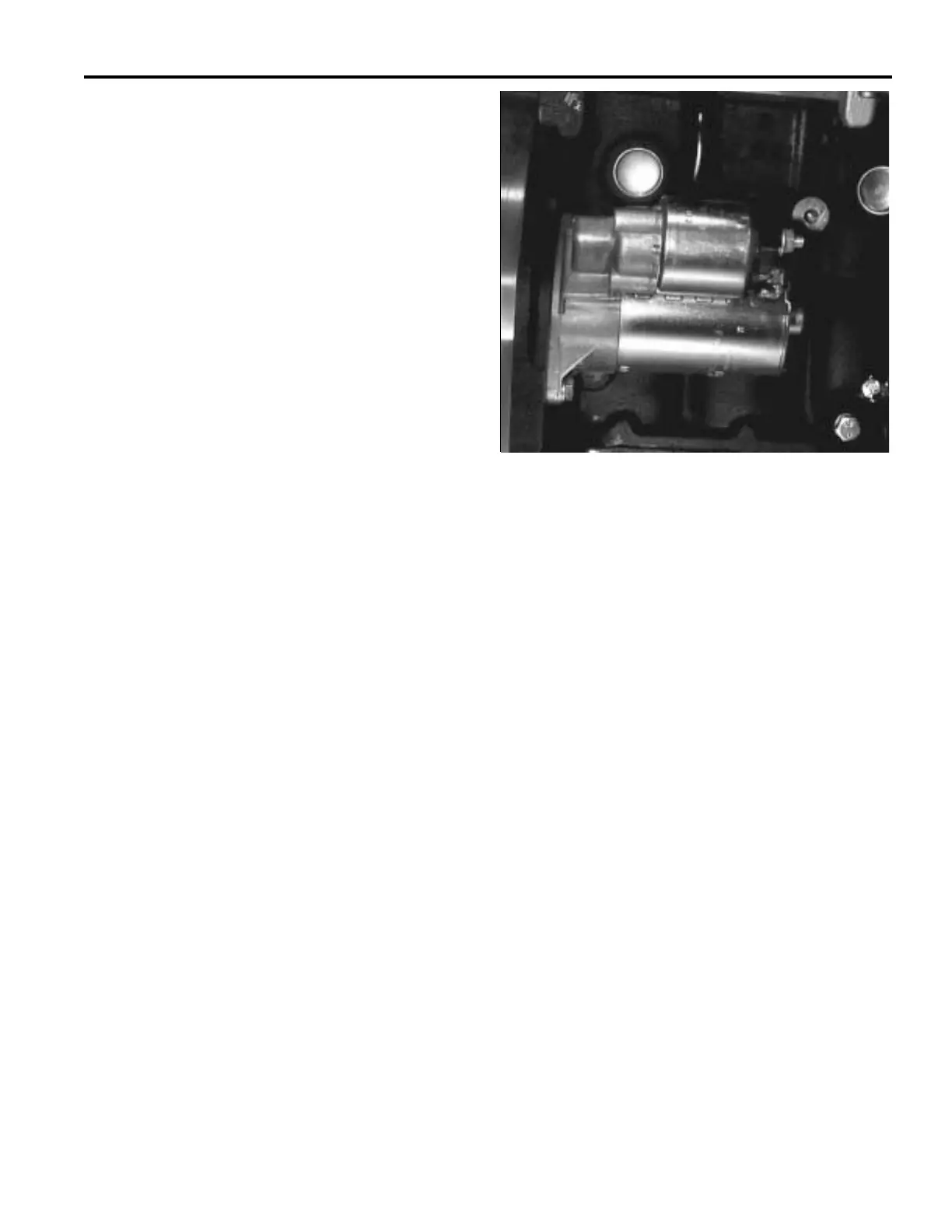
Starter Motor
The 1.6 liter 4-cylinder engine uses a Bosch starter
motor that is considered repairable.
The starter has an over running roller–type clutch and
an enclosed shift lever. The solenoid is sealed in order
to prevent entry of foreign material. The part number is
stamped on a label attached to the field frame.
The shift lever mechanism and the solenoid plunger are
enclosed in the drive housing in order to protect them
from exposure to dirt, icing conditions, and splash.
The solenoid windings energize when the ignition
switch is in the START position. The resulting plunger
and the shift lever movement causes the pinion to
mesh with the engine flywheel ring gear, the solenoid
main contacts close, and the engine cranking takes
place. When the engine starts, the pinion overrunning
clutch protects the armature from excessive speed until
the ignition switch is released, at which time the
plunger return spring causes the pinion to disengage.
In order to prevent excessive overrunning, release the
ignition switch immediately when the engine starts.
With battery voltage applied directly to the starter
motor, the pull–in coil now has voltage applied to both
ends of the coil and current ceases to flow. The starter
solenoid remains engaged due to the current flow
through the hold–in coil alone. The starter motor
continues to operate until the ignition switch is returned
to the RUN position.
With the ignition switch in the RUN position, voltage is
removed from the starter solenoid S terminal. Voltage is
applied at the solenoid B terminal, so both coils are still
energized by battery voltage through the closed motor
contacts. However, the forces from these coil windings
now oppose one another and the plunger returns to the
disengaged position through the operation of the return
spring. This opens the contact within the solenoid to
remove battery voltage from the starter motor and the
motor stops. Both coils also de–energize. This plunger
operation also retracts the starter drive assembly from
the flywheel and the engine operates on its own power.
Starting System Circuit Description
Battery voltage is applied at all times to the starter
solenoid B (battery) terminal through the positive
battery cable.
When the ignition switch is turned to the START
position, battery voltage is applied from the closed
contacts of the ignition switch to S terminal of the
starter solenoid through the BLUE wire.
With voltage applied to the starter solenoid S terminal,
current flows through the hold–in coil to the mechanical
ground at the solenoid. At the same time, current flows
through the pull–in coil and the starter motor to the
starter motor’s mechanical ground. The combined
magnetic force of the coil windings overcomes the force
of the return spring to pull in and hold in the plunger.
The plunger moves the shift lever. This causes the drive
assembly to engage with the engine flywheel.
The plunger actuation also operates a contact within
the starter solenoid which closes to apply battery
voltage directly to the starter motor. The starter motor
now cranks the engine.
80363003