Alpha/Delta (Kinetic Operator) Installation and Maintenance Manual Revision 1 - MAY 2023
139
INSTALLING A MAGLOCK OR SOLENOID LOCK
Installing a MagLock or Solenoid Lock
To provide addional gate security, a maglock or a solenoid lock can be used and connected to the SmartDC
Controller. The SmartDC Controller releases the lock prior to iniang gate movement. Before installing
the lock, be sure to:
• Determine the electrical power requirements of your lock (maglock or solenoid lock). Electronic
board and peripheral connecons dier between high voltage and lower voltage gate operators.
• Determine the current required. A total combined current draw of 1 amp is available from the
24VDC or 12VDC power supply. If the peripherals aached to the terminals need more than 1 amp,
a separate power supply is required. Refer to “Overview of the SmartDC Controller” and “Figure 29.
SmartDC Controller Board” on page 116�
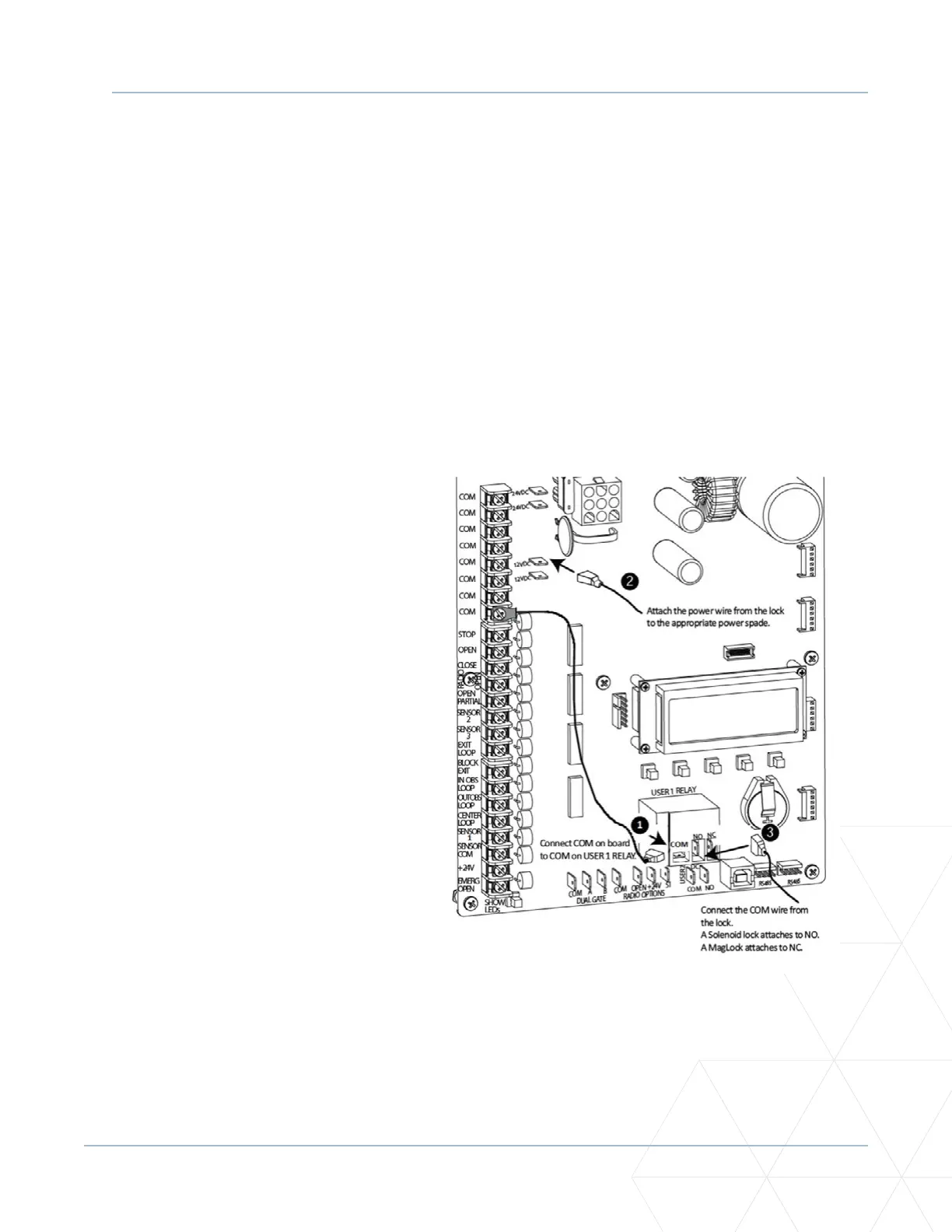
Installing a Lock for 12VDC or 24VDC Systems
To install a lock for 12VDC or 24VDC
systems, take the following steps:
1. Connect a wire between COM on
USER 1 RELAY and a COM terminal on
the electronics board. See Figure37.
2. Make sure to observe polarity and
crimp. Connect the power lead from
the lock to the appropriate power
spade (+24VDC or +12VDC).
3. Connect the common wire from the
lock to NC on USER 1 RELAY.
NOTE: Connect to NO on USER 1 RELAY if
installing a Solenoid lock.
4. Set the User Relay funcon in the
Installer Menu to RL1 - 6. Refer to
“Seng the User Relay Funcon in
the Installer Menu” on page 141.
Figure 37. Lock Installaon 12/24 VDC