94
wallaceperimetersecurity.comPhone: 866.300.1110
USER MENU FUNCTIONS
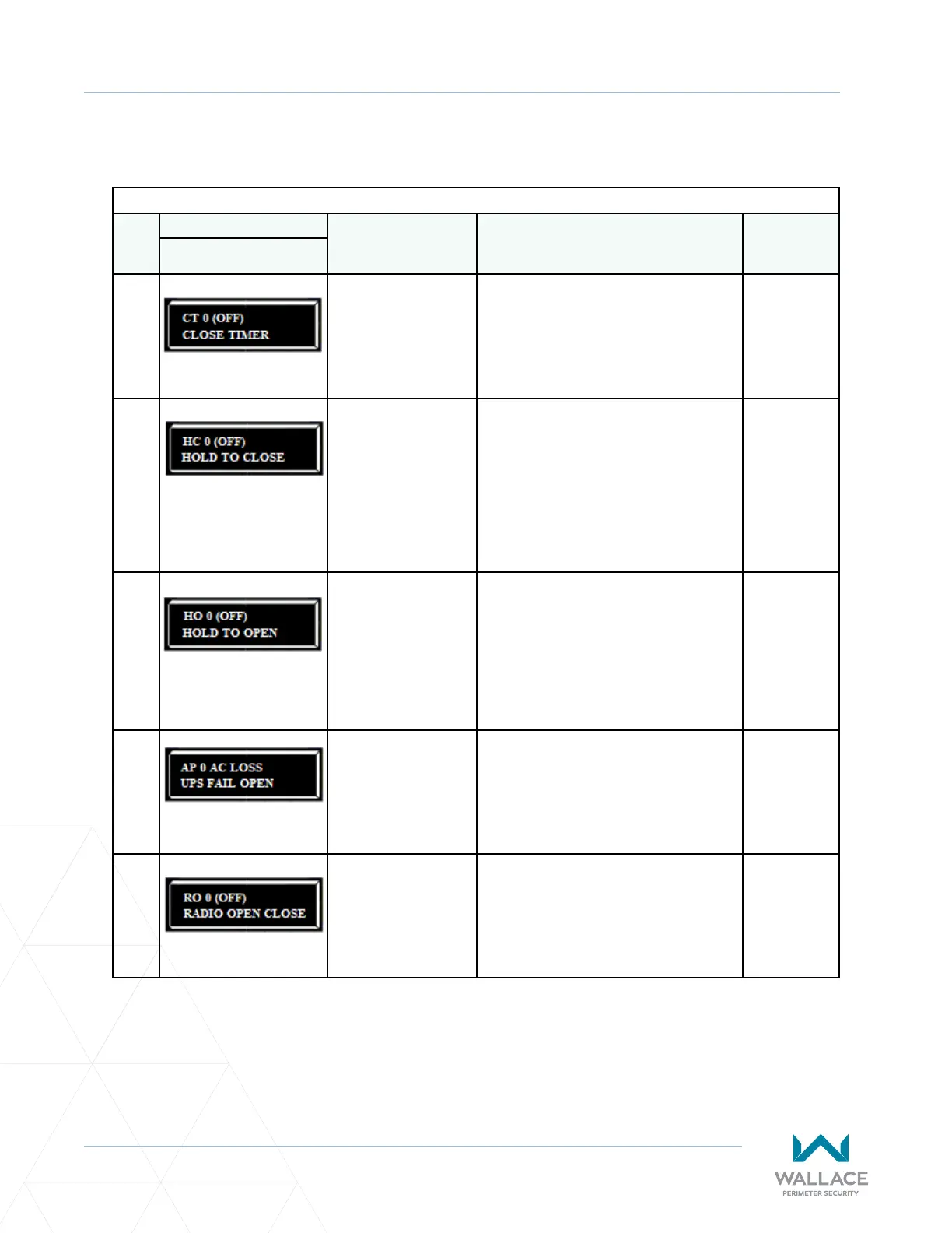
Table 5. SmartDC Controller - User Menu Funcons
Ref.
No�
User Menu Seng Opons
(Bold = Factory
Sengs)
Menu Tasks and Explanaons
Associated
DC Controller
Connecons
Display
1
CT 0 (OFF)
CLOSE TIMER
0 = Timer disabled
1 second to 99 seconds
Assign how many seconds before the open
gate iniates closure.
Keep the seng at 0 if a hard-wired, push-
buon control device is being used.
Note: The CLOSE TIMER display does not
appear when the HOLD TO CLOSE is set to 1.
Not applicable
(N/A)
2
HC 0 (OFF)
HOLD TO CLOSE
0 = o
1 =on
Set to 0 produces a gate closure when a
momentary signal is transmied.
Set to 1 if a constant hold to close signal,
such as a push-buon control, is being used.
A seng of 1 also deacvates the automac
close mer and causes its menu to disappear.
You must set HC to 1 to comply with UL 325
Type D protecon. Refer to “Table Notes” on
page 97.
COM
CLOSE
3
HO 0 (OFF)
HOLD TO OPEN
0 = o
1 =on
Similar to HOLD TO CLOSE, but congures
the OPEN push-buon for a constant-hold
funcon.
0 = Momentary open signal
1 = Constant hold OPEN push-buon
required. You must set HO to 1 to comply
with UL 325 Type D protecon.
Refer to “Table Notes” on page 97.
COM
OPEN
4
AP 0 AC LOSS
UPS FAIL OPEN
0 = UPS FAIL OPEN
1 = UPS FAIL CLOSE
2 = AUTO OPEN
3 = NO CLOSE TIMER
The seng designates what acon the gate
performs during an AC power loss.
Refer to “Seng AC Power Loss Gate
Funcon” on page 92.
(N/A)
5
RO 0 (OFF)
RADIO OPEN CLOSE
0 = o
1 = on
Congures radio input for open only (0). If
changed to seng 1 then adds the capability
for radio input to close the gate, but only
when the gate is fully open.
COM
RADIO OPEN
USER MENU FUNCTIONS