138
wallaceperimetersecurity.comPhone: 866.300.1110
REFERENCE
Reference
This secon of the manual provides informaon which may be useful when installing Kinec operators. It
includes how to:
• Connect a Radio Receiver for Remote Open
• Install a Gate Locking Mechanism
• Set User Relay Funcons
• Install Vehicle Detectors and Loops
• Install Photoelectric Sensors
• Install Gate Edge Sensors
• Troubleshoot Error Codes, Faults, and
Hardware Issues
• Diagnose Vehicle Detector and Loop Faults
• Handle General Maintenance Procedures
Connecng a Radio Receiver for Remote Open
Take the following steps to mount a commercial style 24VDC radio receiver (external antenna type):
1. Install the receiver in the channel of the chassis on either side of the control box.
2. Knock out the closest hole in the boom of the control box and route the wires to the area marked
RADIO OPTIONS. Only three wire connecons are needed because the common wire and one radio
output wire are connected together. Figure 36 shows addional wires from a two-channel receiver.
3. Make sure to observe polarity and crimp together the black radio common wire and one of the radio
output wires using a ¼ -inch spade connector.
4. Fasten the two crimped wires to the COM terminal.
5. Connect the red wire to the +24V spade and connect the other radio output contact wire to the spade
marked OPEN.
NOTE: This terminal is the same as the input terminal labelled RADIO OPEN along the le edge of the
SmartDC Controller.
6. Mount an external antenna onto the top of a xed fence post near the operator.
7. Connect the antenna into the socket on the radio receiver.
8. Set the “DIP” switches in the receiver to match the same code used in the transmier.
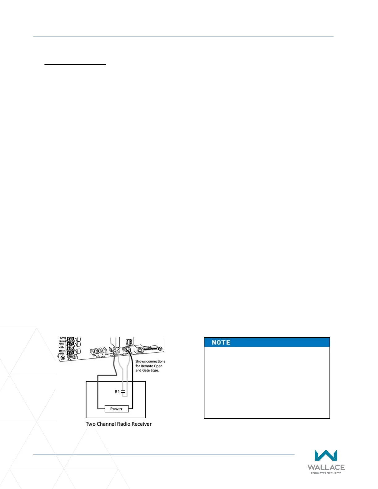
Figure 36. Addional Wires from Two-Channel Receiver
If an edge sensor transmier is also
used to reverse the gate, be certain
to use a two-channel commercial
receiver. The edge and handheld
transmiers must have their codes
set to match the receiver or they will
not funcon.