148
wallaceperimetersecurity.comPhone: 866.300.1110
INSTALLING GATE EDGE SENSORS
Installing Gate Edge Sensors
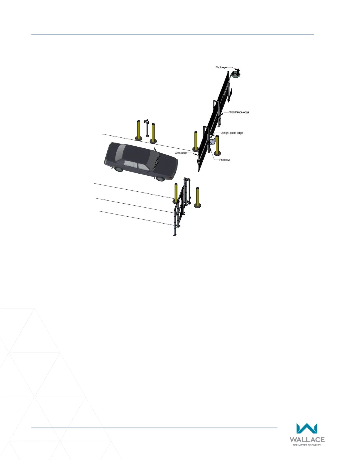
Refer to Figure 44 to help plan the most appropriate placement of the edge sensors being installed. For
sliding gates, one or more contact sensors (edge sensors) must be located at the leading edge, trailing
edge and post-mounted both inside and outside of the sliding gate. Three-sided detectors are ideal for
slide gates. If the clearance of the gate is 6 inches (15cm) or more above the road, then an edge sensor
must be mounted on the boom edge. Underwriters Laboratories requires that any contact sensor used
as an external entrapment protecon device, must be laboratory tested to, and recognized by, the UL 325
Standard.
Drill holes through the edge's mounng channel and through the surface that each gate edge is to be
mounted. Securely fasten every edge sensor. Protect the area wherever a potenal pinch point exists for
any type of entrapment. Ensure all exposed pinch points are eliminated or guarded.
Edge sensors that are not aached to the moving gate, such as post mounted sensors, must be wired in
parallel and directly connected to the gate operator:
• If the gate is sliding open to a wall with less than 16" (41cm) of clearance, mount an edge sensor to
the wall that aligns with the gate when it is in the open posion. Always route the leads from the edge
sensors to the gate operator so that they are protected from physical damage.
• An oponal receiver connecon method is to connect one edge sensor lead to a COM terminal at the
top, le side of the SmartDC Controller, and the other lead to the EDGE terminal, at the boom le
side of the controller.
Figure 44. Gate Edge Sensor Installaon