106
wallaceperimetersecurity.comPhone: 866.300.1110
INSTALLER MENU FUNCTIONS
INSTALLER MENU FUNCTIONS
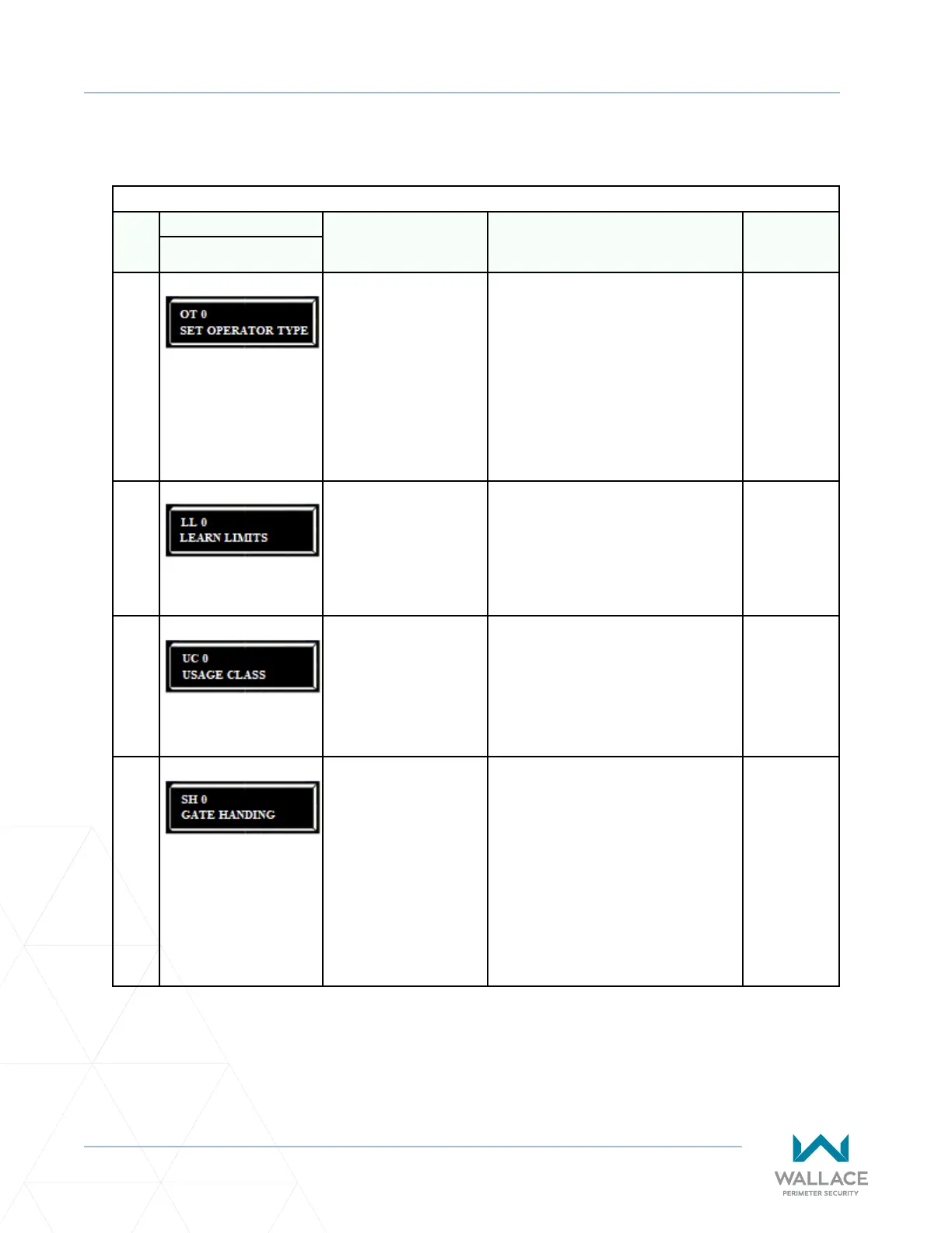
Table 6. SmartDC Controller - Installer Menu Funcons
Ref.
No�
Installer Menu Seng Opons
(Bold = Factory Sengs) Menu Tasks and Explanaons
Associated
DC Controller
Connecons
Display
1
OT 0
SET OPERATOR TYPE
0 = operator type
15 = Kinec 1 (DC 15)
& Solar
16 = Kinec 2 (DC
10F)
& Solar
Select the appropriate number for the
operator. Note: This menu item only
appears if the SmartDC Controller is
being replaced.
CAUTION: If you are replacing an
SDC board, remember to transfer the
operator’s menu sengs from the
exisng board to the replacement board.
Refer to the installaon instrucons that
accompany the replacement SDC board.
Not applicable
(N/A)
2
LL 0
LEARN LIMITS
0 = Normal operaon
1 = Reset limits
A seng of 1 places the operator into its
learn limits mode which allows you to
reset the gate’s open and close posions.
Refer to “Reseng the OPEN and CLOSE
Limits” on page 99.
(N/A)
3
UC 0
USAGE CLASS
0 = Gate disabled
1 = Residenal 1 to 4 units
2 = Comm./public access
3 = Light industrial
4 = Industrial secure
Assign the operator’s Usage Class
designaon per UL 325 standards. See
“Idenfying Gate Operator Category and
Usage Class” on page 27. The installer
must designate a usage class before the
operator will funcon. See “Programming
the Inial Setup Menu” on page 61.
(N/A)
4
SH 0
GATE HANDING
0 = Gate disabled
R = Right hand
L = Le hand
The handing determines which way the
gate opens as you view it from the secure
side. The installer must designate a le
or right handing before the operator will
funcon. See “Programming the Inial
Setup Menu” on page 61.
(N/A)