Alpha/Delta (Kinetic Operator) Installation and Maintenance Manual Revision 1 - MAY 2023
117
PRELIMINARY TESTING
Preliminary Tesng
All the control device inputs listed in Table 7 are shown as a single input. The second wire is connected to
a Common Terminal Bus (1 - 8) on the SmartDC Controller board.
The Fire Department Open input is an excepon and requires a +24VDC input as well as acvaon through
the Installer Menu.
For convenience a +24VDC terminal is located next to the EMERG OPEN terminal. See “Figure 29. SmartDC
Controller Board” on page 116. Note that programming in the User or Installer Menu is required for
most connecons.
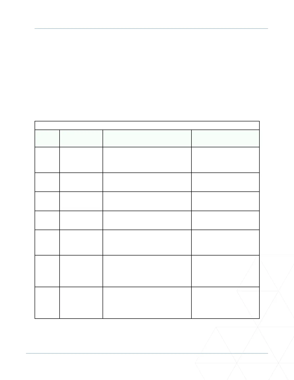
Table 7. SmartDC Controller Board Inputs
Terminal
No�
Label/Input
Name
Wire Connecon Uses
1 - 8 Common
Terminal
All user inputs are energized when
connected to common except
Emergency Open.
All inputs except Emergency
Open.
9 Stop * push
buon
Normally Closed (N.C.) input. Jumper
to Common if not being used.
Line of sight, external stop
buon or 3-buon staon.
10 Open * push
buon
Normally Open (N.O.) input. Not for
radio or remote access controls.
Line of sight, external open
buon or 3-buon staon.
11 Close push
buon
N.O. input. Connecon for a close
push-buon.
Line of sight, external close
buon or 3-buon staon.
12 Remote Open
and Radio
Control**
N.O. input. For radio/remote open or
close device – Access the User Menu
and program RO RADIO OPEN/CLOSE.
Remote access control or
radio controls.
13 Paral Open N.O. input. This input will cause the
gate to open to Paral Open posion
programmed in the Installer Menu (7-
32).
Supervised access controls.
14 Sensor 2 N.C. input. Connecon of a Monitored
External Entrapment sensor. Type
of sensor used is programmable in
Installer Menu (S2).
External entrapment sensors.