Alpha/Delta (Kinetic Operator) Installation and Maintenance Manual Revision 1 - MAY 2023
71
WIRING 115VAC POWER
Wiring 115VAC Power
For standard 115VAC power connecon:
• Verify AC power supply wires and low voltage (12V & 24V accessory power wires) run through
two separate conduits. The higher voltage from the AC power supply may cause interference
and anomalies in Kinec operaon if the high and low voltage wires are routed through the same
conduit.
• Maximum gate system current draw is 3 amps on a dedicated 115VAC circuit (20A dedicated circuit
is recommended).
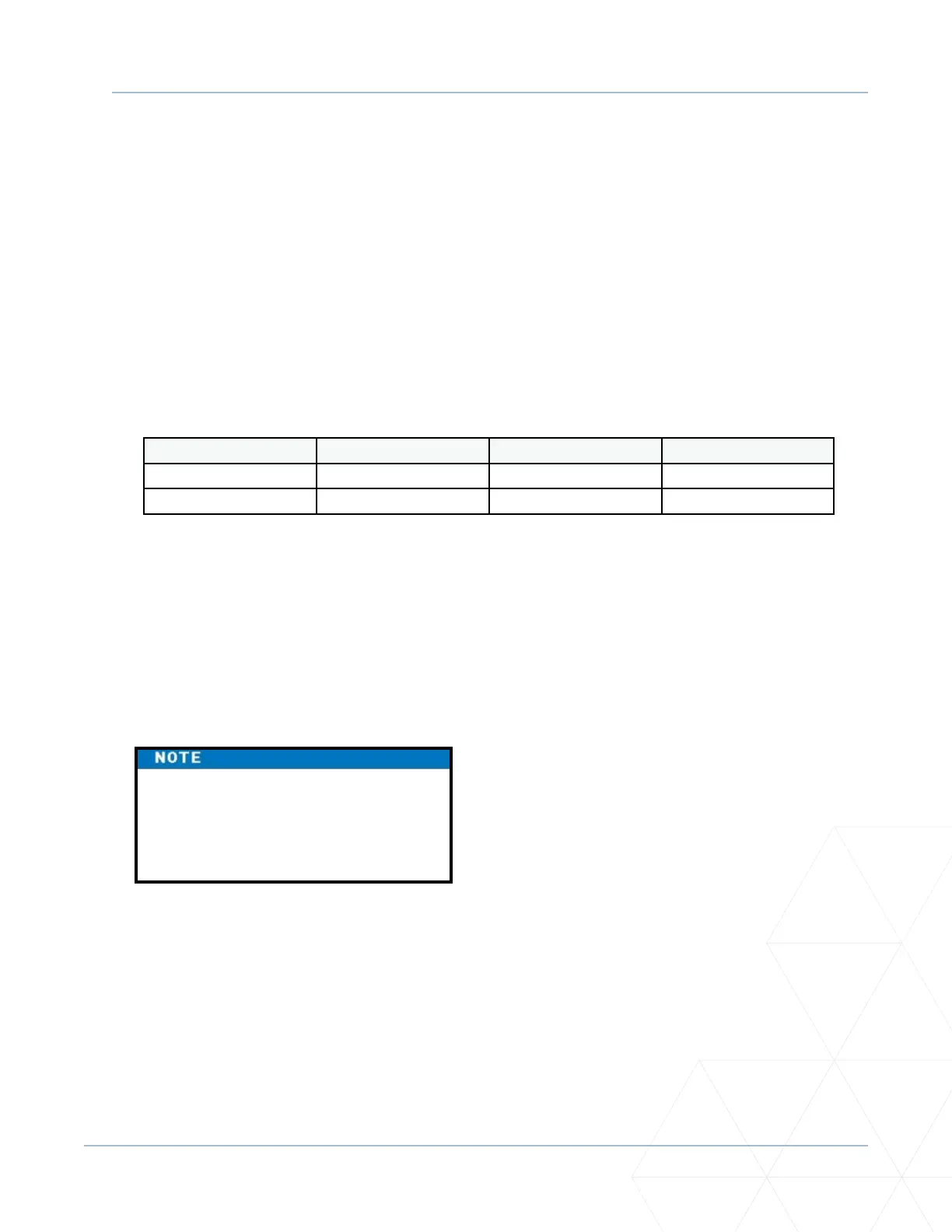
• Make sure the proper wire size is used. The following table shows the maximum allowable wire run
from the power source to the operator for various wire sizes.
AC Power 14-gauge wire 12-gauge wire 10-gauge wire
One operator 115V 730 (223 m) 1200 (366 m) 1900 (579 m)
Two operators 115V 460 (140 m) 750 (228 m) 1160 (354 m)
Table 2. Wire Gauge versus Run
Table 2 assumes a dedicated circuit with an accessory power load up to 2A. Addional loads require that
the wire size be increased or the distance of the run be decreased.
To connect to 115VAC power, take the following steps:
1� Make sure the AC power is turned o at its source and the DC and AC power switches on the operator
are in the OFF posion.
2� Access the input power wires and service outlet wires by removing the two Phillips-head screws
that secure the high voltage juncon box cover. See “Figure 16. Wiring AC Power” on page 70.
3� Wire nut or crimp bond the power supply wires to the black and white lead wires coming from the
AC power switch (no label). See Figure 16.
4� Wire nut or crimp bond the equipment ground wire to the green ground wire in the juncon box.
5� To acvate the 115VAC service outlet, include the black and white outlet lead wires and the green
ground wire in the connecons made above.
6� Neatly organize all wire connecons and replace the high voltage juncon box cover. Secure it
with the two Phillips-head screws.
The service outlet wires are solid
copper and are labelled and bound
together to keep them separate from
the AC power switch wires.