Alpha/Delta (Kinetic Operator) Installation and Maintenance Manual Revision 1 - MAY 2023
83
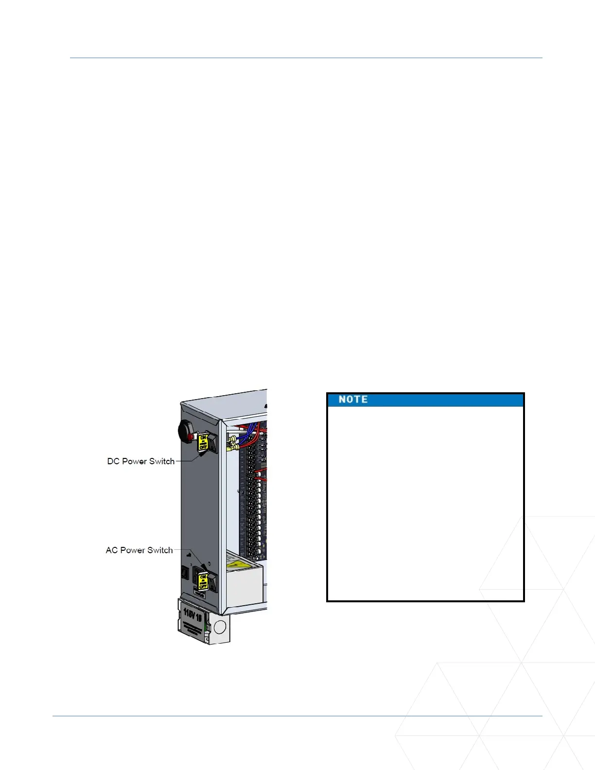
TURNING BOTH POWER SWITCHES ON
Turning Both Power Switches On
AC and DC power switches are located on the outside edge of the control box. See Figure 22. Aer
Programming the Inial Setup Menu, Establishing the OPEN and CLOSE Limits, Installing the Target Magnet,
and connecng to main power (Power), take the following steps:
1. Turn both power switches ON. The gate moves and searches for the target magnet to re-establish
the limits. An audible beep occurs and a red light pulsates next to the OPEN buon on the SmartDC
Controller which indicates the system is funconing. If AC power is lost, the rate of ashing slows
down. Other indicator lights are described below.
NOTE: If the target magnet is not detected by the operator, “ALERT 15 - NO TARGET” or “LEARN
OPEN” appears on the display. For more informaon, refer to “Installing the Target Magnet” on
page 66�
2. When the target magnet is detected, the soware version briey appears on the display, and then one
of the following modes appears:
• Gate status - indicates the operator is in Run Mode. Refer to “RUN MODE” on page 86.
• Alert, fault, and error messages - indicates a problem exists with the operator which needs to be
resolved before the operator can funcon properly. Refer to “SmartDC Controller Troubleshoong”
on page 151.
The SmartDC Controller can be
powered when either switch is turned
on. If the DC power switch is OFF the
motor and baeries are disconnected.
The operator will not funcon (even
though the AC power switch remains
on). When the operator is connected to
AC power and both switches are turned
ON, the charge level of the baery is
being monitored and maintained. On
a solar-powered operator, the lower
power switch connects and disconnects
the DC power from the solar panels.
Figure 22. AC and DC Power Switches