84
wallaceperimetersecurity.comPhone: 866.300.1110
TURNING BOTH POWER SWITCHES ON
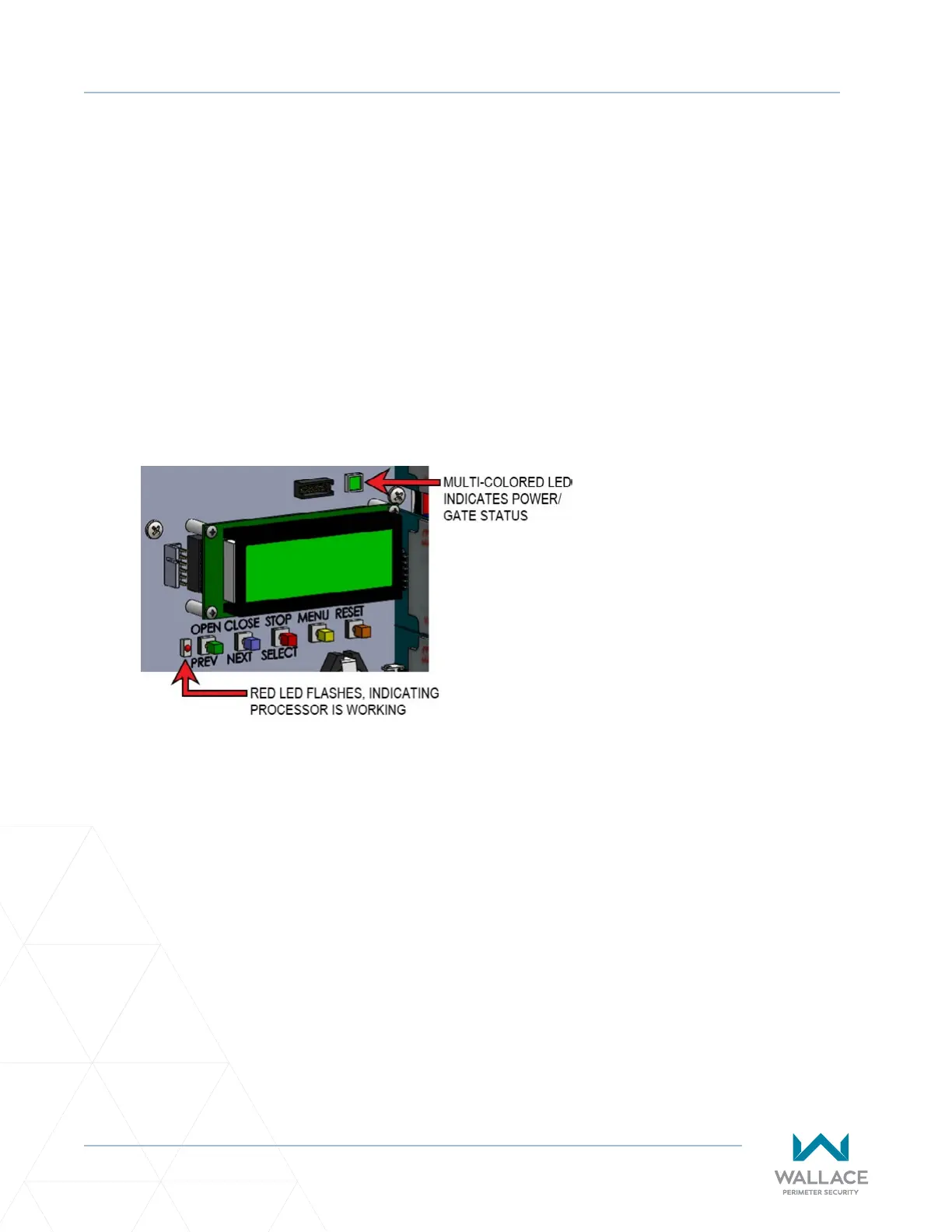
The ashing red indicator light next to the OPEN buon on the SmartDC Controller is considered the
‘heart’ beat of the system. It indicates that the electronics board is receiving power. When AC power is
lost, the rate of ashing slows down.
Another indicator light, above the display, is mul-colored and corresponds to the acon that the operator
is performing:
• Green – the operator is stopped.
• Flashing Yellow – the operator is running.
• Red – the operator has experienced an error.
• Not lit - AC power is lost. Pressing the SHOW LEDs buon indicates which inputs, if any are acve.
Refer to Figure 23 for SHOW LEDs locaon on board.
Figure 23. LED Indicators