28
wallaceperimetersecurity.comPhone: 866.300.1110
CHOOSING EXTERNAL ENTRAPMENT PROTECTION
Choosing External Entrapment Protecon
The site designer or installer must determine which external entrapment sensor devices will be installed
with the Kinec operator to meet UL compliance. The type(s) of entrapment sensor device systems are
described below. For a complete lisng of the requirements, see UL 325 Safety Standards.
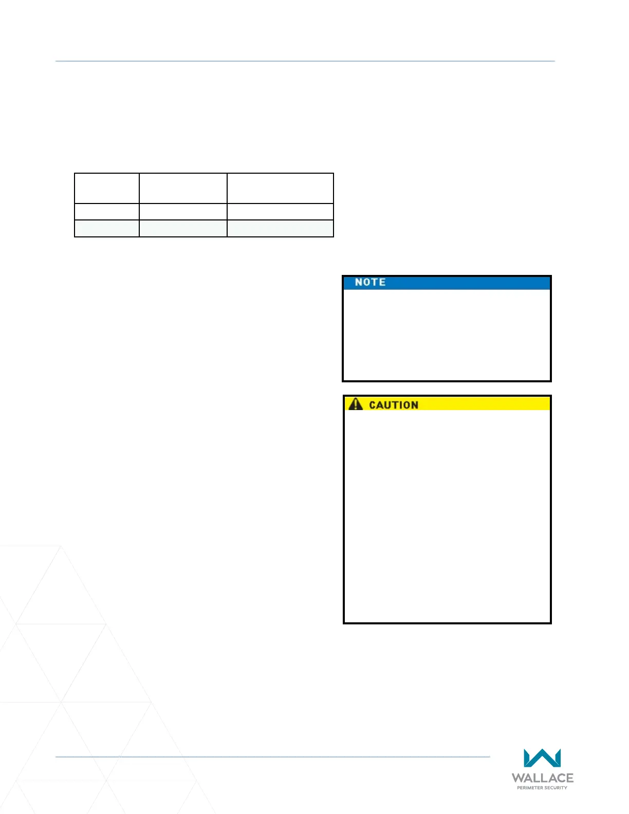
Usage Class Inherent Type
Device
External Type Device
Class I, II, III A B1, B2, C, or D
Class IV A B1, B2, C, D, or E
The Kinec system is equipped with
a Type A inherent entrapment sensor
(IES) that complies with UL 325. Any
impediment to gate travel causes the
gate to stop and reverse.
Compliance issues exist with a Type E
device (audible warn before operate
alarm). A Type E device is permied
as a means of external entrapment
protecon by UL 325 in Class IV
applicaons, but it is not recommended
by Wallace Perimeter Security because
a buzzer warns, but cannot protect
against possible entrapment. Wallace
Perimeter Security highly recommends,
even for Class IV use, that external
entrapment protecon (edge or photo-
eye sensor) devices be installed to
detect possible entrapment.
To comply with UL 325, refer to the chart and take
the following steps:
1. Select the Usage Class according to the gate’s
locale and purpose.
2. The required UL 325 inherent Type A sensor is
an integral part of the Kinec system.
3. Based on the gate’s usage class, choose
External Type Devices: B1, B2, C, D, or E.
• To comply using B1 - install non-contact
sensors (photoelectric sensor or the
equivalent).
• To comply using B2 - install contact
sensors (edge sensor device or the
equivalent).
• Refer to the following Secon for the
operator manufacturer’s list of (non-
contact and contact) tested sensors
compliant with the UL 325 Standard of
Safety.
• Mounted beyond 6 feet (183cm) of the
gate, to prevent users from touching or
accessing the gate.
• To comply using a Type D device requires
a CONSTANT HOLD push-buon staon.
This CONSTANT HOLD push-buon
staon must be the only device that
opens and closes the gate. It can only
be used where the gate and push-buon
staon will be monitored by personnel
24 hours a day in full view of the gate
area. An automac closing device (such
as a mer, loop sensor, or similar device)
must not be employed. A Warning
placard stang, “WARNING - Moving
Gate has the Potenal of Inicng
Injury or Death - Do Not Start the Gate
Unless the Path is Clear” must be placed
adjacent to the gate operator control.