64
wallaceperimetersecurity.comPhone: 866.300.1110
TARGET SENSOR RACK DRIVE INSTALLATION INSTRUCTIONS
Target Sensor Rack Drive Installaon Instrucons
The following instrucons are intended to assist the user in the new Wallace Kinec gate operators target
sensor rack drive kit installaon, available from Wallace Perimeter Security. To order, ask for Kit Part No.
951WG-WH). The new rack drive kit provides a fender washer and zinc collar to secure the target sensor
past the operator’s outer cover and close distance between sensor and chain magnet, minimizing any
posioning challenges. No tools are required.
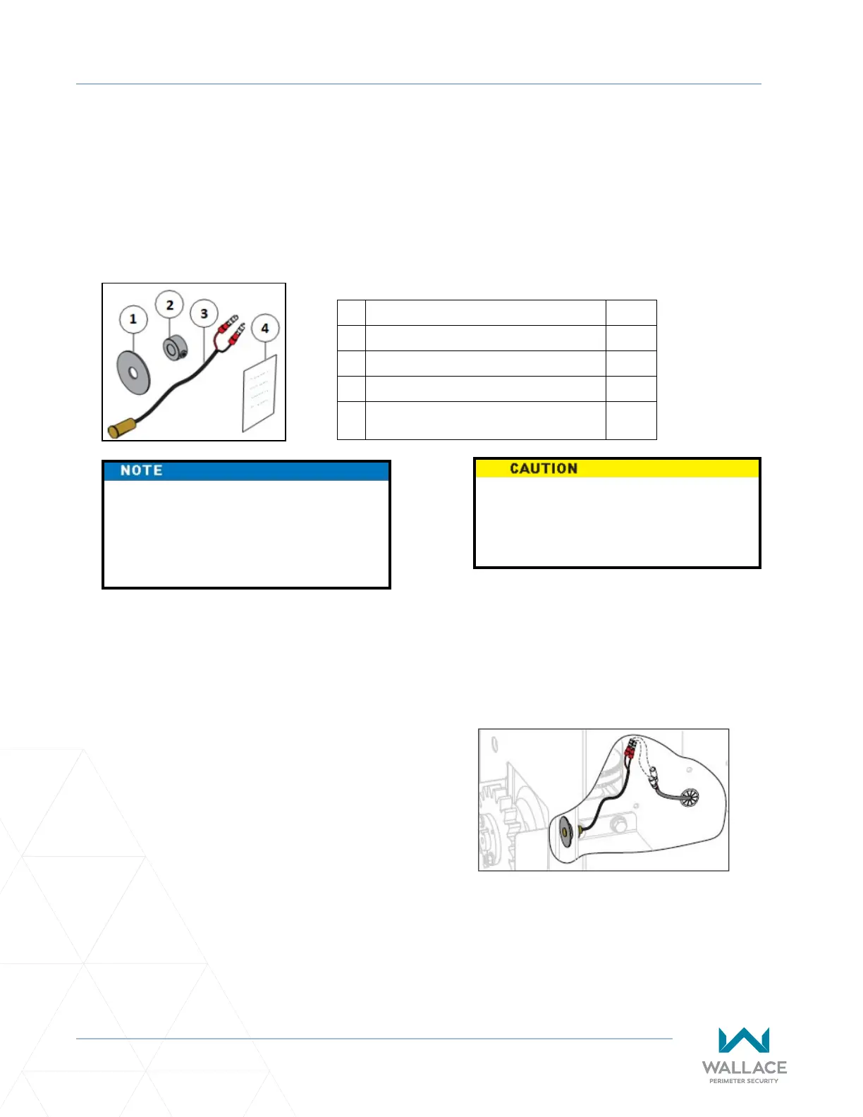
Item Qty
1. Washer, Fender 1
2. Collar, 3/8" Sha, Zn 1
3. Sensor, Magnec Proximity 1
4.
Wallace Target Sensor Rack Drive
Installaon Instrucons
1
Wallace Rack Drive Ship-With Kit
Only a qualied service technician with
proper training should perform this
installaon. Follow all shop safety rules
when performing this installaon.
Preparaon:
1. Make sure AC and DC power is turned o.
2. Unlock, remove, and set aside front cover.
3. Back cover may remain installed.
4. Determine if target magnet sensor will be
installed on the le or right of operator.
Target Magnet Sensor Assembly:
1. Slide fender washer onto magnec proximity
sensor unl fender washer and sensor are
ush. See Figure A.
2. Route connected fender washer and target
sensor through operator chassis outer cover.
See Figure B.
3. Slide and secure 3/8” sha zinc collar to target
sensor back to secure fender washer and
target sensor. See Figure C.
4. Connect target sensor male connectors to
appropriate female connectors. See Figure D.
DO NOT overghten zinc collar to
target sensor, or you may damage
target sensor.
Fully Installed Target Magnet Sensor
Post Installaon Tesng
1. Turn AC and DC power on.
2. Reset and test limits as needed.