Alpha/Delta (Kinetic Operator) Installation and Maintenance Manual Revision 1 - MAY 2023
145
INSTALLING PHOTOELECTRIC SENSORS FOR EXTERNAL ENTRAPMENT PROTECTION ONLY
Installing Photoelectric Sensors for External Entrapment
Protecon Only
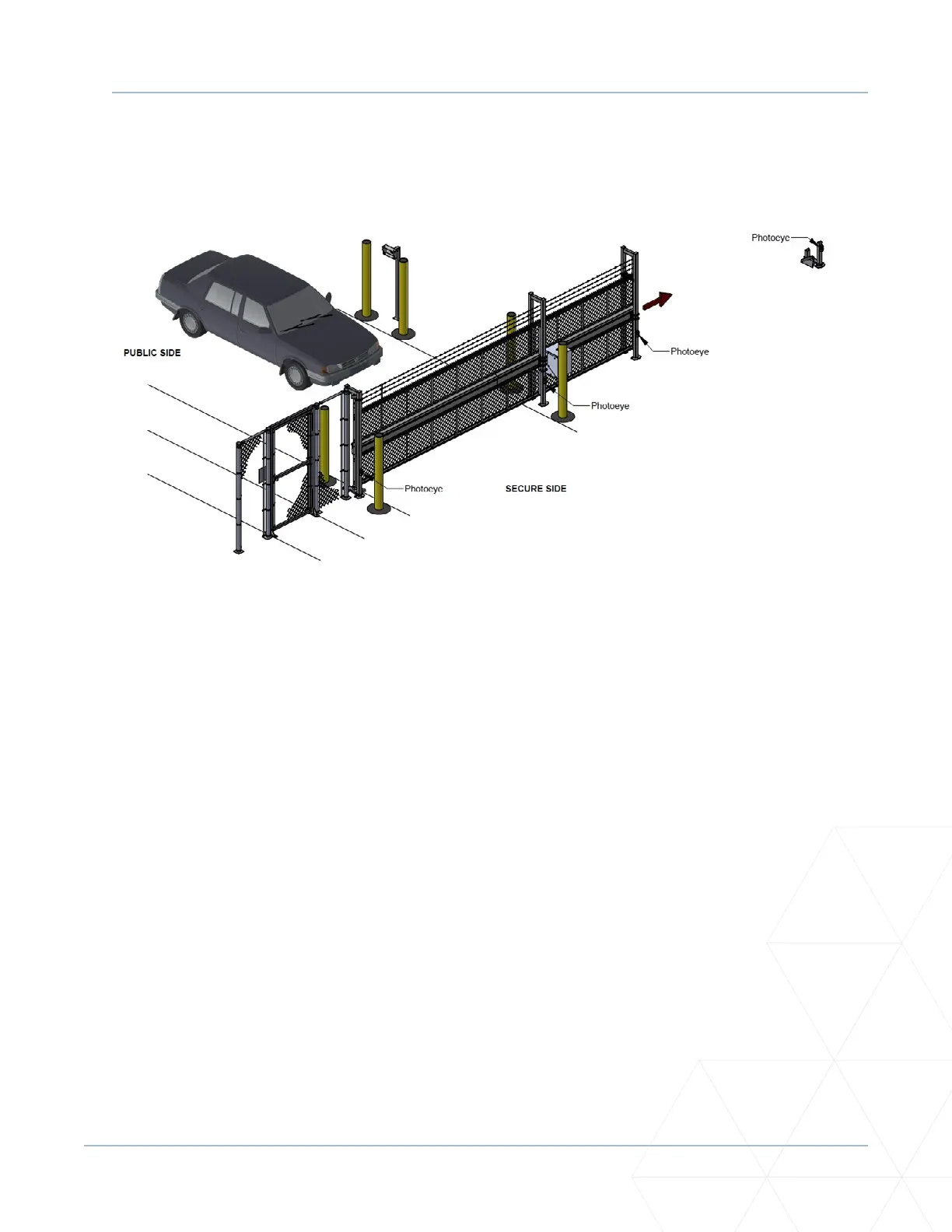
Refer to Figure 42 to help plan the most appropriate placement for the photo eyes being installed as
external entrapment protecon devices. If no other external entrapment protecon devices (like edge
sensors) are installed, then at least two photoelectric sensors are required to guard the gate in each
direcon of travel. If the photo eyes are tripped, the operator will temporarily stop the gate.
Consult a photoelectric sensor manual for wiring details. Make all electrical connecons to SmartDC
Controller as shown in Figure 43 on the next page.
Operaon Notes
• A photo eye trip does not reverse gate.
• The SmartDC Controller soware is factory set to stop upon photo eye trip.
• Soware is congurable to stop and reverse two seconds upon photo eye trip.
If the photo eye is cleared within ve seconds, the gate will proceed in the direcon of travel.
The SmartDC Controller has three sensor inputs (Sensor 1, Sensor 2, Sensor 3) which can be used for any
type of photoelectric inputs. See “Figure 43. Connecons for Entrapment Protecon Only” on page
146. Underwriters Laboratories requires that any non-contact sensor used as an external entrapment
protecon device, must be tested to, and recognized by, the UL 325 Standard.
There are two common types of photoelectric sensors, thru-beam and retro-reecve, and each has its
advantages.
Figure 42. Photoeye Placement as External Entrapment Protecon Devices