146
wallaceperimetersecurity.comPhone: 866.300.1110
OPERATION NOTES
• A thru-beam sensor is generally more powerful and able to funcon reliably with dirty opcs and in
poor weather.
• A retro-reecve sensor does not require the installaon and extra wiring of a separate emier and
receiver as is required in a thru-beam system, but retro-reecve eyes are generally more problemac
in poor weather. Avoid using retro-reecve devices across outdoor distances greater than 24 feet
(7.3m) because of performance and reliability issues.
Mount thru-beam type photo eyes approximately 15” to 30” (.38m to .76m) above the ground and as
close to the gate as possible. A minimum of two photo eyes are required, one photo eye to guard the
open direcon and the other for the close direcon of travel, unless gate edges for entrapment protecon
are installed. Mount the emiers and the receivers just beyond the travel of the gate in both the full open
and full closed posions of travel. The installaon locaons described above are intended for pedestrian
detecon. If photo eyes are to be used for vehicular detecon, install a low elevaon photo eye for cars
and another photo eye at a height of about 55” (140cm) to detect semi-trucks.
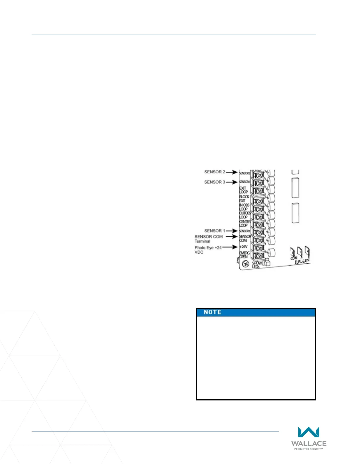
Figure 43. Connecons for Entrapment
Protecon Only
If the photo eye has an internal switch for
seng Light Operate vs. Dark Operate, select
Light Operate. If the photo eye has a relay
output and has both NO and NC terminals, some
experimentaon may be required to determine
the proper connecon. This is because, in the
Light Operate mode, the output relay is normally
energized and releases when the beam is blocked.
Some manufacturers label an output as NO, when
it is actually an NC contact. If the photo eye has a
solid-state output you must choose a sinking type
connecon.
Three wires to the receiver and two wires to the
emier are all that is required.
• Depending on how the photo eyes are to be
wired, +24VDC or +12VDC, power is provided
via spades located just to the right of the COM
terminal strip near the le side of the board.
Wire all eyes to 24V or all to 12V; do not mix
voltages.
• The receiver common wire is connected to the
SENSOR COM terminal at the boom le of
the SmartDC Controller. The emier common
wire is connected to the COM terminal at the
top le of the controller.
• The photo eye NC output wires connect to the
SmartDC Controller at the appropriate Sensor
Input (1, 2, or 3).
If photo eyes are to be used for
vehicle detecon and logically
funcon the same as a vehicle
detector, connect the common wires
to the COM terminals on the le
side of the board and wire the NO
output contact to the appropriate
vehicle detector input: EXIT LOOP,
IN OBS LOOP, and OUT OBS LOOP.