Alpha/Delta (Kinetic Operator) Installation and Maintenance Manual Revision 1 - MAY 2023
143
INSTALLING VEHICLE DETECTORS AND LOOPS
9. This guide is wrien from a design perspecve, but installaon workmanship pracces are equally
important to ensure proper operaon and long loop life. The best way to ensure a quality installaon
is to employ a professional installer experienced with detector loops. A few important pracces are:
• The slot in the surface of the road should be cut ¼-inch wide x 1½-inch deep (6.3 x 38.1mm).
• The corners of the cut must be at an angle or core drilled to relieve stress on the wires.
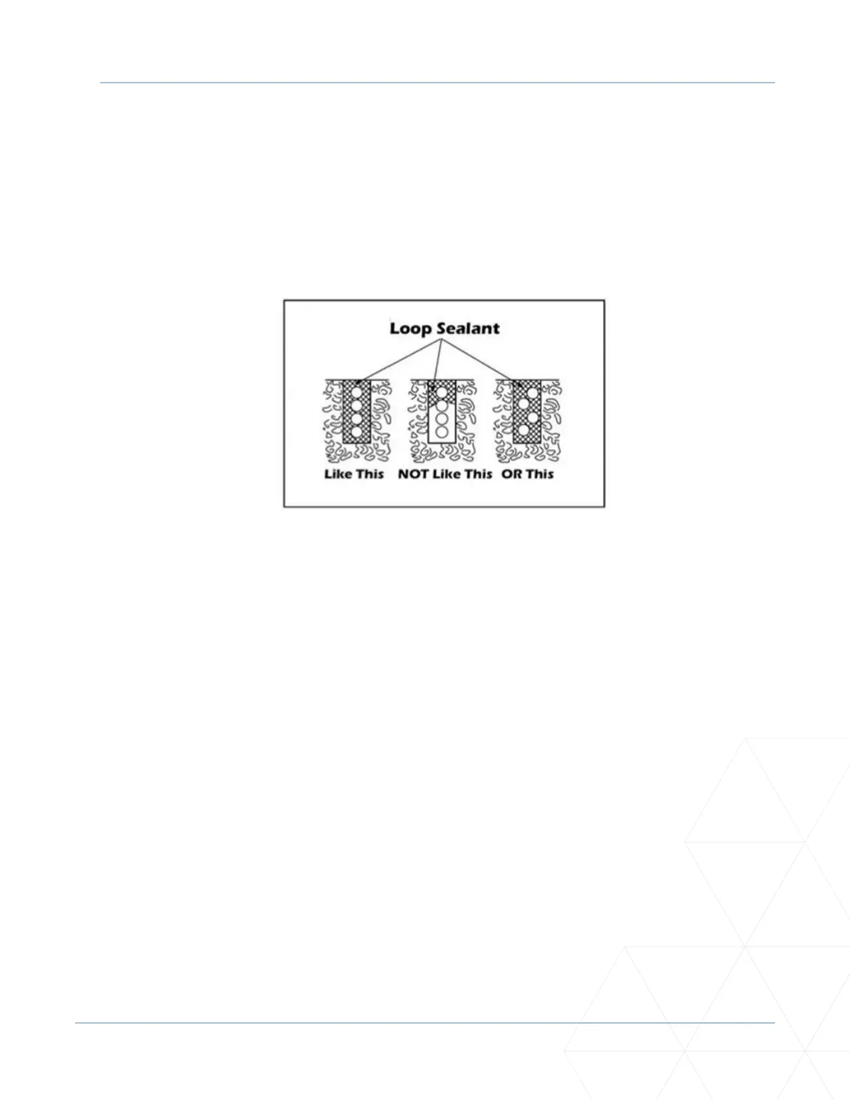
• Aer the wire is installed, the slot must be completely backlled with a non-hardening sealer. If
the loop wires are able to move in the slot aer the sealer has set, the detector may give false
calls.
Figure 40. Loop Sealant Applicaon
Detector Logic
HySecurity recommends that vehicle detectors be used for free open and obstrucon sensing logic only.
Because of their slower speeds, closing logic is a poor choice for security gate systems. Since there are
several ways that the gate may be le standing open and because there is a loss of safety, our circuit has
not been designed to accommodate “detect to close” logic.
Loop Diagnoscs
The following tests cannot guarantee a funconing loop, but failure of either test means that the loop is
denitely suspect, even though it may sll be funconing at the me.
1. Test the resistance of the loop and lead-in wire. It should not exceed 4 ohms.
2. Test the resistance between the loop and earth ground with a 500V Megohmmeter. It should be 100
Megohms or more. Loops may funcon at less than 100 Megohms but will not be reliable (e.g., when
the ground is wet from rainfall). Low resistance indicates broken or moisture-saturated insulaon.
This is common if inappropriate wire insulaon has been used.
A schemac for a slide gate loop layout is shown in Figure 41.