150
wallaceperimetersecurity.comPhone: 866.300.1110
ACCESSORY CONNECTIONS
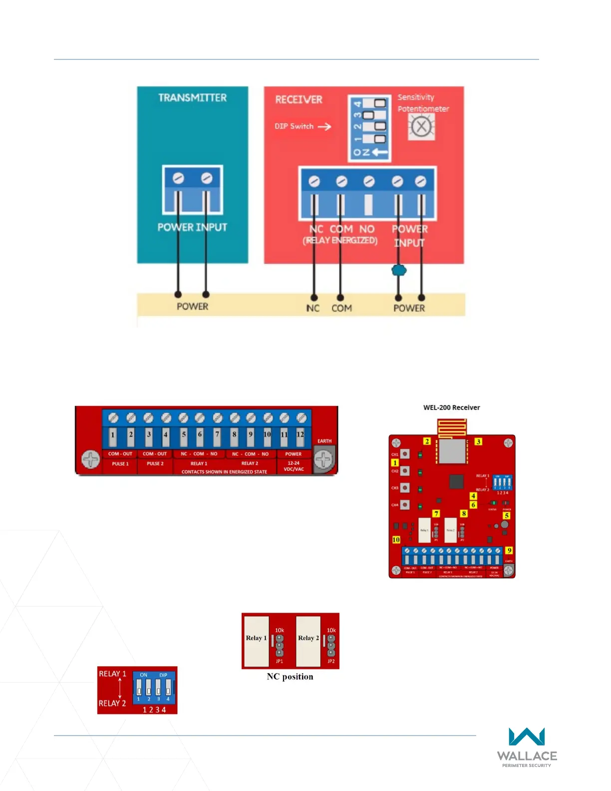
An Edge Sensor can be either hardwired through an adapter module (HY2NC) or a wireless transmier/
receiver combo (WEL-200 or iGAZE RE). Figure 46 below shows the wiring and dip switch sengs of a
WEL-200.
Figure 45. EMX-IRB-MON Photo Eye Wiring
Receiver Connecons:
1. Channel assignment buons
2. Channel LEDs
3. Radio
4. DIP switch
5. Power LED
6. System Status LED
7. Relay 1 - 10K Jumper
8. Relay 2 - 10K Jumper
9. Earth ground
10. Terminal block
Normally Closed Monitoring: Connect Power Wires Last
• For channels assigned to Relay 1, connect the sensor common to
terminal 6, and the operator input (sensor 1, 2 or 3) to terminal 5.
• For channels assigned to Relay 2, connect the sensor common to
terminal 9, and the operator input (sensor 1, 2 or 3) to terminal 8.
• For NC, move the jumper on the receiver to the top two pins.
• Connect 24 VDC to terminal 11 and sensor COM to terminal 12.
On the DIP switch, indicate which
channels will output through Relay 1
and Relay 2 terminals. The DIP switch
in the image shows all four channels
outpung through Relay 2 terminals.
Figure 46. WEL-200 or iGAZE RE