Maintenance1203−1/A1
Winterthur Gas & Diesel Ltd.
2/ 2
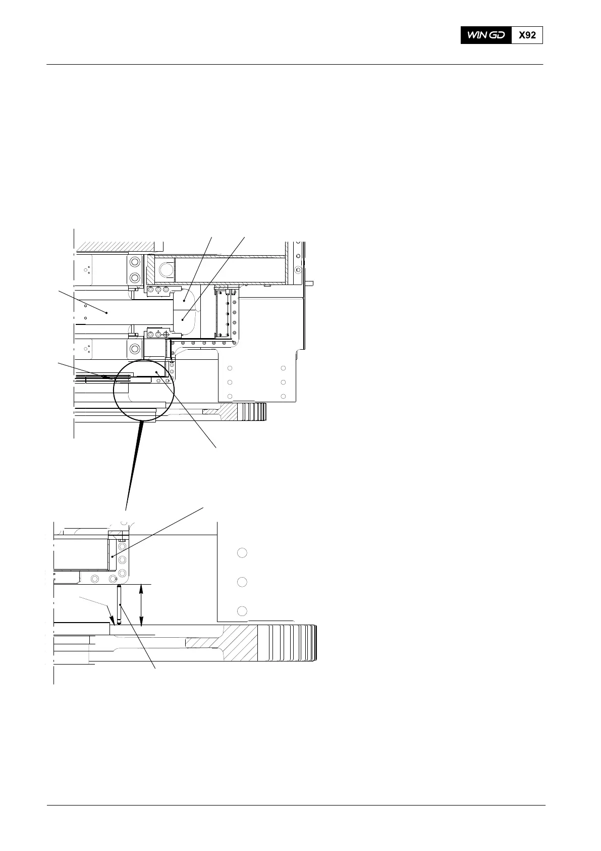
2. Procedure Two
1) Start the engine in the direction AHEAD
to move the crankshaft fully forward.
The crankshaft (4, Fig. 2) must touch
the thrust pads (1).
2) Stop the engine.
3) Make sure that the crankshaft (4) does
not move.
4) Use the micrometer 94101 to measure
the distance between the crankshaft
flange (4) and the oil baffle (2).
5) Record the value.
6) Remove the micrometer 94101.
7) Compare the value with those given in
the engine documents on the Check
Dimensions page(see also the 0330−1
Clearance Table, Crankshaft and
Thrust Bearing).
The difference between the distance X and
the value given in the engine documents is
related to the wear of the thrust pads (1).
8) Start the engine in the direction
ASTERN to move the crankshaft fully
forward. The crankshaft (4) must touch
the thrust pads (5).
9) Stop the engine.
10) Make sure that the crankshaft does not
move.
11) Use the micrometer 94101 to measure
the distance between the crankshaft
flange (3) and the oil baffle (2).
12) Record the value.
13) Remove the micrometer 94101.
14) Compare the value with those given in
the engine documents on the Check
Dimensions page (see also the 0330−1
Clearance Table, Crankshaft and
Thrust Bearing).
The difference between the distance X and
the value given in the engine documents is
related to the wear of the thrust pads
(5, Fig. 1).
Checking the Axial Clearance
2015
Fig. 2
X
94101
3
2
WCH02761
3
2
15
4