Maintenance1903−1/A1
Winterthur Gas & Diesel Ltd.
2/ 3
3. Tie Rods − Replacement
3.1 Preparation
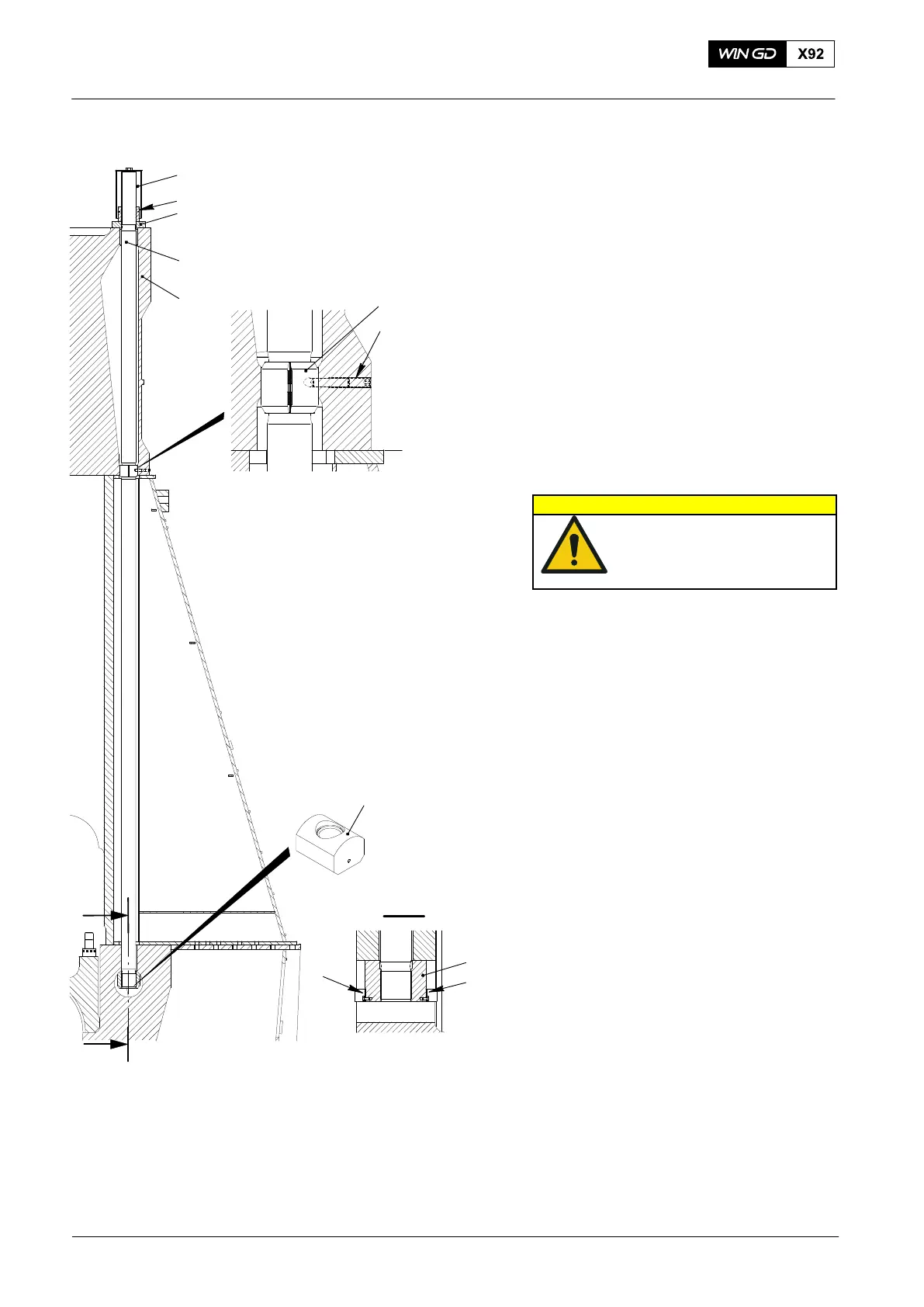
1) Remove the protection cover (1, Fig. 2)
from the tie rods (4).
2) Clean the surface of the intermediate
ring (3).
3) Refer to 9403−4, then attach the two
pre-tensioning jacks (94180) to two tie
rods that opposite each other (e.g.
a−a), see Fig 1.
4) Loosen the round nuts (2), refer to
9403−4.
3.2 Removal
1) Remove the two set screws (7, Fig. 2).
2) Use two round nuts screwed together
to remove the tie rod (4).
3) Attach an applicable eye bolt to the top
of the tie rod (4).
CAUTION
Injury Hazard: The weight
of the tie rod is 318 kg. Use
the correct equipment for
removal.
4) Attach the hook of the engine room
crane to the eye bolt.
5) Lift the tie rod (4) fully from the cylinder
jacket (5).
3.3 Install
1) Remove the two holders (10).
2) Make sure that the nut (8) is correctly
attached.
3) Apply Molykote G paste to the bottom
thread of the tie rod (4).
4) Attach an applicable eye bolt to the top
of the tie rod (4).
5) Attach the hook of the engine room
crane to the eye bolt.
6) Make sure that the bush (6) is installed.
7) Lower the tie rod (4) into the cylinder
jacket (5).
8) Turn the tie rod (4) until the bottom is
flush with the bottom of the nut (8).
9) Clean the top surfaces of the cylinder
block (9).
10) Install the intermediate ring (3).
11) Add Molykote G paste to the top thread
of the tie rod (4) and the top surface of
the intermediate ring (3).
12) Attach the round nut (2) to the tie
rod (4).
13) Lift the tie rod (4), then fully tighten the round nut (2).
14) Make sure that the nut (8) is fully up, then install the holders (10).
Note: The tie rod at the first cylinder (driving end) has only one holder (10).
15) Apply tension to the tie rods (1), refer to paragraph 3.4.
Pre-tension Checks and Tie Rod Replacement
2015
Fig. 2
WCH02762
1
8
10
4
1
2
3
5
8
WCH02347
I - I
I
I
7
6