Maintenance
2708−1/A1
Winterthur Gas & Diesel Ltd.
5/ 6
4. Cylinder Cover, Water Guide Jacket, Exhaust Valve −
Installation
For installation of the exhaust valve, refer to
2751−1 and 2751−2.
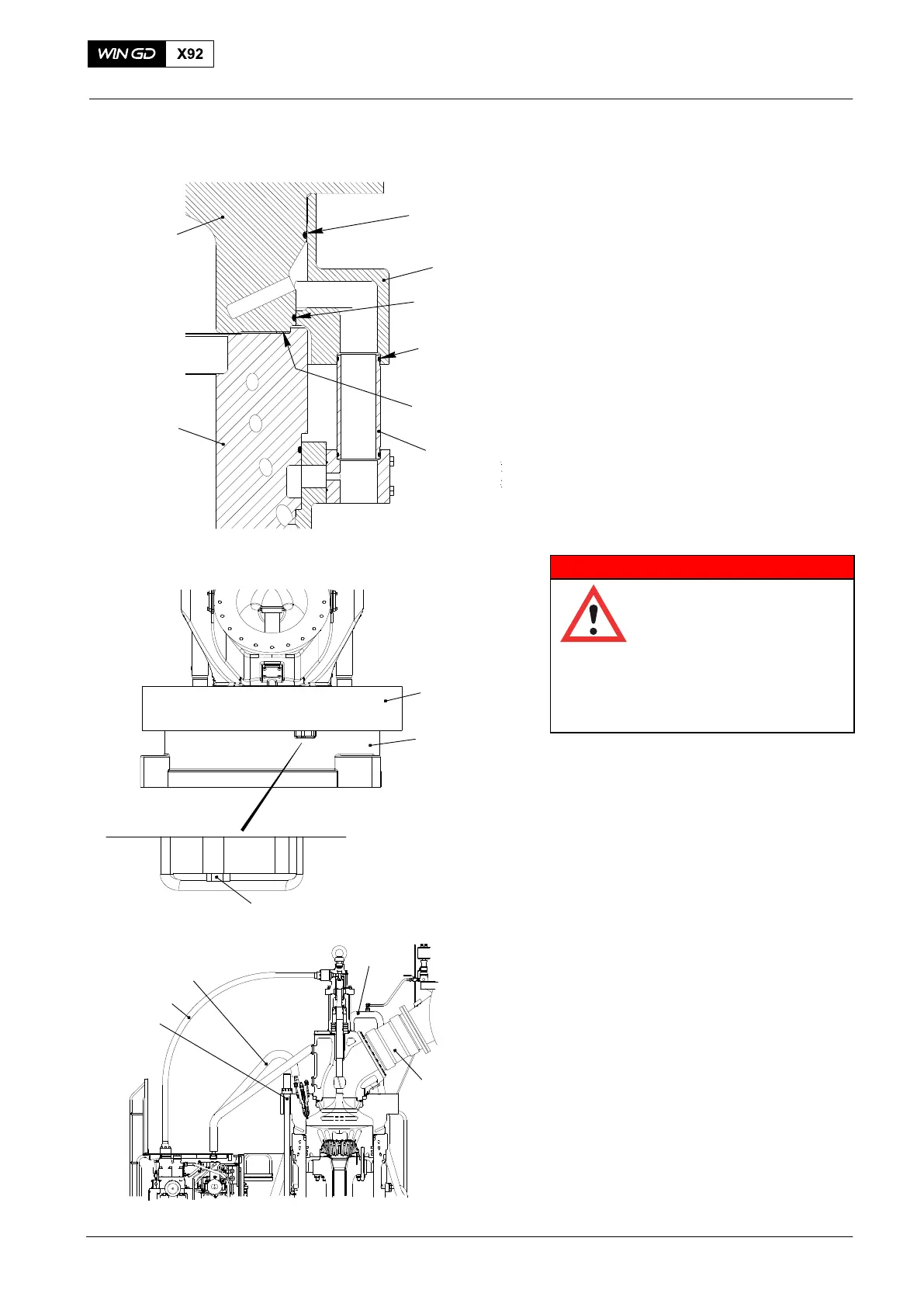
1) Clean all contact faces and O-ring
grooves.
2) Apply oil to two new O-rings (3, Fig. 7)
and install them.
3) Lift the cylinder cover (1) and guide it
into the top water guide jacket (2). See
also chapter 3.
4) Tighten the retaining screws M12x50
(7, Fig. 8).
5) Clean the seating surface of cylinder
liner (5, Fig. 7) and put a new soft iron
joint ring (4) in position.
6) Install the new O-ring (6, Fig. 7) on the
transition tubes (8) and apply oil to it.
WARNING
Injury Hazard: Heavy parts
can fall down. Do not stand
under the hanging parts.
Injury to personnel can oc-
cur. Heavy parts can crush
body parts. Always use
correct personal protective
equipment.
7) Lift the cylinder cover (1) in accordance
with paragraph 3 and clean the lower
seating face.
8) Bring the cylinder cover (5) in position
over the cylinder liner (5) that the
transition tubes (8) are in line with the
same bore of the water guide jacket
(2).
9) Carefully lower the cylinder cover (1)
and guide the transition tubes (8) into
the water guide jacket (2).
10) Tension the elastic studs (3, Fig. 9),
refer to paragraph 2.
11) Install the hydraulic pipe (4) for exhaust
valve drive, refer to: 8460−1.
12) Install the three HP fuel pipes (5), refer
to 8733−1.
13) Connect the cooling pipe (1).
14) Install the expansion piece (2) with
round slings, refer to 2751−1.
2021
Removal and Installation of Cylinder Cover, Water Guide Jacket, Exhaust Valve
3
WCH02942
1
4
5
2
Fig. 7
3
6
4
3
WCH02934
Fig. 8
7
8
3
4
5
1
2
WCH02926
Fig. 9
2021