Maintenance2751−1/A1
Winterthur Gas & Diesel Ltd.
4/ 4
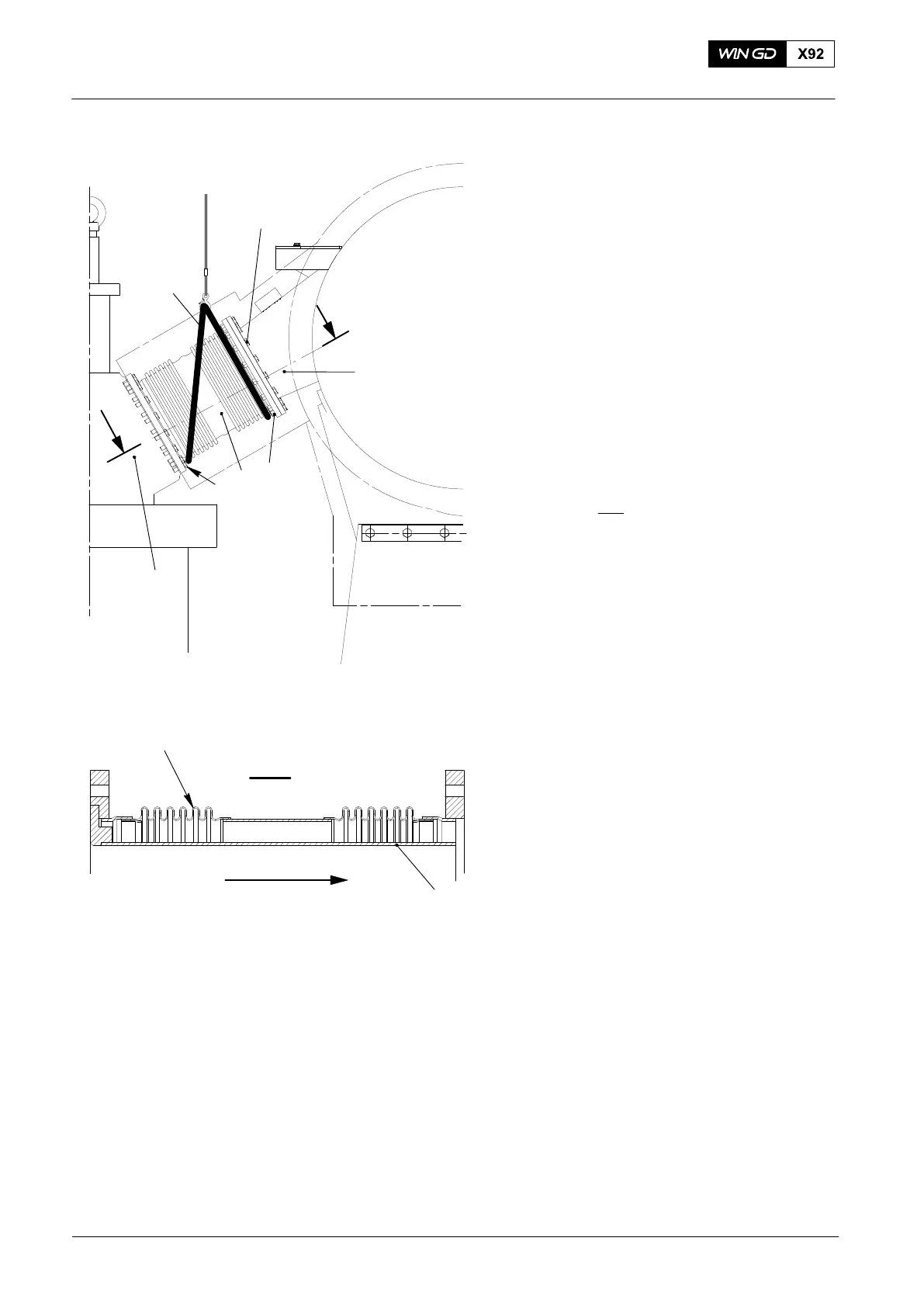
15) Clean the sealing contact surfaces of
the expansion piece (6) and the related
faces on the valve cage (3) and
exhaust pipe (14, see Fig. 7).
16) Apply a thin layer of heat-resistant
lubricant to the sealing faces and the
screws (12 and 10).
17) Put the slings (94049A) in position on
the expansion piece.
18) Connect the slings to the hook on the
crane.
19) Use the crane to lift the expansion
piece (6).
20) Put the expansion piece in position
between the valve cage and the
exhaust pipe. Make sure that the
direction of flow is correct see
view I − I
.
21) Install the screws (10) and (12) and
nuts (11).
22) Remove the slings.
2015
Exhaust Valve − Removal and Installation
Direction of Flow
I
I
I - I
7
6
WCH02964
WCH02353
14
Fig. 7
10
11
12
6
94049A
14
3