Maintenance
3303−2/A1
Winterthur Gas & Diesel Ltd.
7/ 8
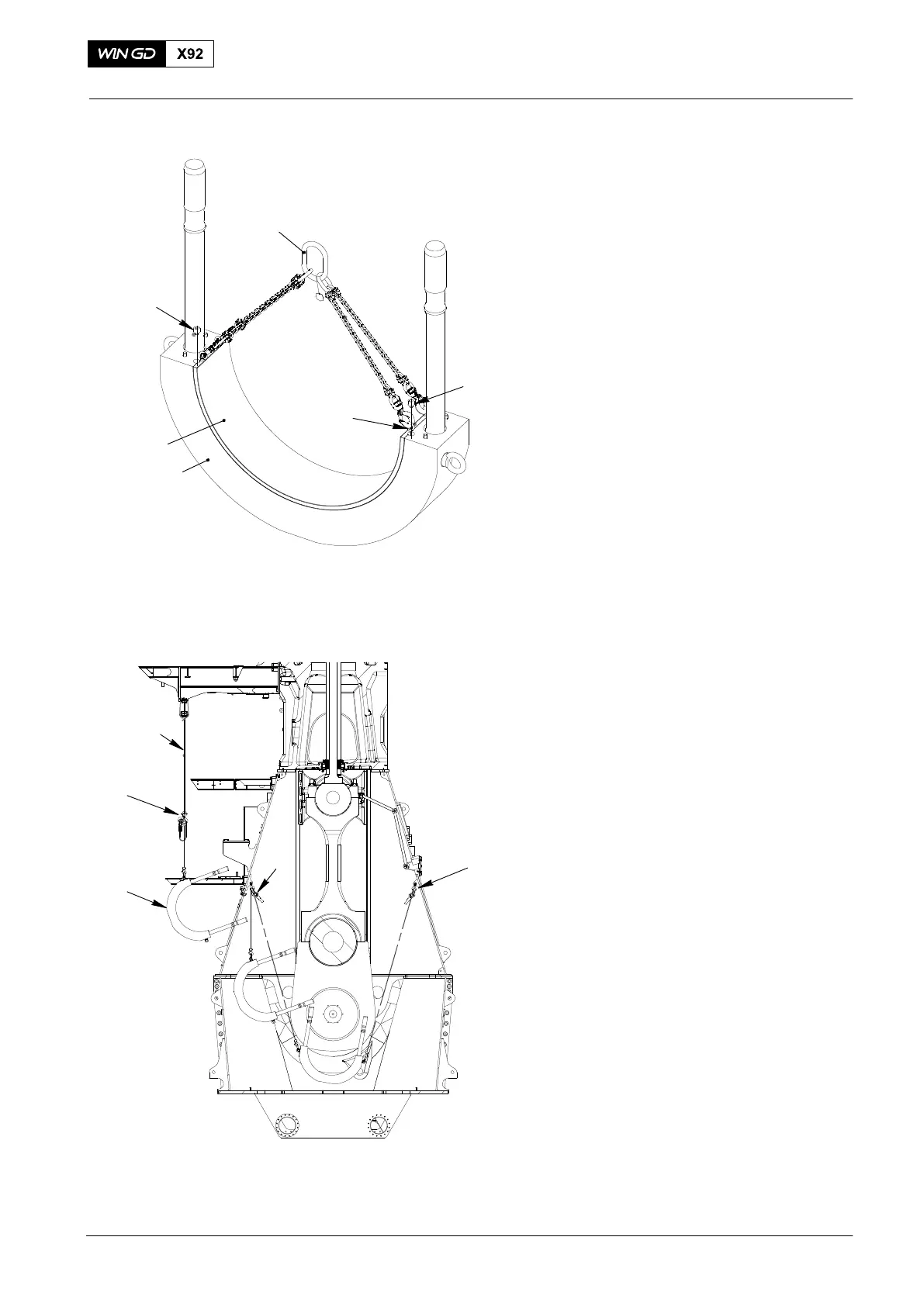
7. Bottom Bearing Shell −
Installation
1) Attach the four eye bolts 94045-M10,
(Fig. 11) to the bottom bearing shell (3).
2) Attach the chain 94327 to the four eye
bolts 94045-M10.
3) Lift the bottom bearing shell (3).
4) Clean the seating surface of the
bearing cover (2) and the bearing
shell (3).
5) Put oil on the surface of the bearing
shell (3).
6) Attach the bottom bearing shell (3) to
the bearing cover (2) with the four
screws (1).
Note: Make sure that the distance
between each end of the bearing
shell and the connecting rod rod is
the same.
7) Remove the chain 94327 and the four
eye bolts 94045-M10.
8. Bearing Cover −
Installation
1) Attach the chain 94038−15 (Fig. 12) to
the gallery.
2) Attach the manual ratchet (H4) to the
chain 94038-15 and the eye bolt on the
bearing cover (1).
3) Move the bearing cover (1) into the
crankcase.
4) Attach the manual ratchets (H2, H3) to
the column and the bearing cover (1).
5) Remove the manual ratchet (H4).
6) Operate the manual ratchets (H2 H3) to
lift the bearing cover (1) into position.
2015
Bottom End Bearing − Removal, Inspection and Installation
1
1
94327
2
94045-M10
3
Fig. 11
Fig. 12
WCH03013
FUEL SIDE
WCH03013
H2
H4
EXHAUST SIDE
94038−15
H3
1