Maintenance3303−2/A1
Winterthur Gas & Diesel Ltd.
6/ 8
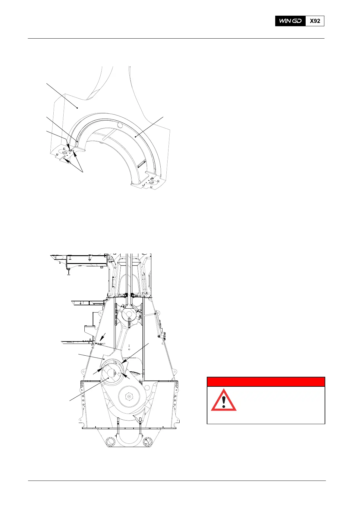
6. Top Bearing Shell −
Installation
1) Clean the seating surface of the
bearing shell.
2) Put the bearing shell on the console
frame 94326 (Fig. 9), then tighten the
four screws (2).
3) Clean the seating surface of the
connecting rod (4) and the bearing
shell (3).
4) Attach the manual ratchet (H4) to the
console frame 94326.
5) Operate the manual ratchet (H4) to lift
the console frame 94326 into position.
6) Attach the manual ratchets 94016−012
(H5, H1, Fig. 8) to the console frame
94326.
7) Remove the manual ratchet (H4).
8) Put oil on the surface of the bearing
shell.
9) Operate the manual ratchets (H1, H5)
to move the console frame 94326 and
bearing shell into position.
Note: Make sure that the distance
between each end of the bearing
shell and the connecting rod rod is
the same.
10) Attach the bearing shell (3, Fig. 9) to
the connecting rod (4) with the two
screws (2).
11) Remove console frame 94326.
12) Make sure that the surface of the crank
pin (2, Fig. 10) is in a satisfactory
condition.
13) Put oil on the crank pin.
WARNING
Injury Hazard: Before you
operate the turning gear,
make sure that no
personnel are near the
flywheel.
14) Use the turning gear to move the crank
to TDC. At the same time, make sure
that there is no load at points (X).
15) Remove the two supports 94322 and
94322A (Fig. 4).
2015
Bottom End Bearing − Removal, Inspection and Installation
Fig. 9
Fig. 10
WCH03013
94326
3
2
1
H3
1
2
3
X
X
WCH03013
4