Maintenance
3303−2/A1
Winterthur Gas & Diesel Ltd.
3/ 8
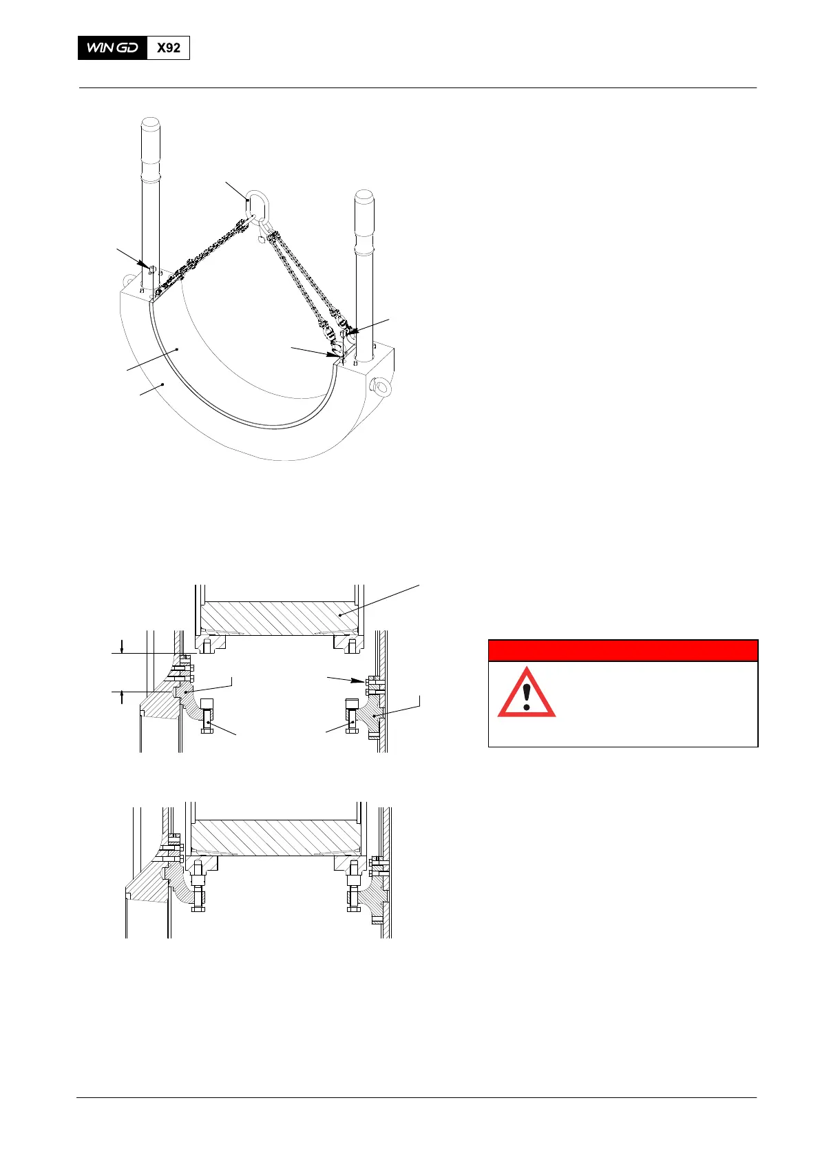
3. Bearing Shell −
Removal
1) Remove the two screws (1, Fig. 3).
2) Install the four eye bolts 94045-M10.
3) Attach chain 94327 to the four eye
bolts 94045-M8.
4) Lift the bearing shell (3) from the
bearing cover (2).
4. Top Bearing Shell −
Inspection
WARNING
Injury Hazard: Before you
operate the turning gear,
make sure that no
personnel are near the
flywheel.
1) Unlock the turning gear.
2) Use the turning gear to turn the crank
to the fuel side until the crosshead (1,
Fig. 4) is approximately 300 mm above
the plug bore.
3) Put oil on the four bolts(2).
4) For 6−7 Cylinder engines: Attach the
two supports 94322 and 94322A with
the four bolts (2).
5) For 8−12 Cylinder engines: Attach two
supports 94322A with the four bolts (2).
6) Tighten the special screw (3) on each
support.
7) Use the turning gear to lower the
crosshead (1) on to the special screws
(3).
2015
Bottom End Bearing − Removal, Inspection and Installation
1
1
94327
2
94045-M10
3
Fig. 3
WCH03013
WCH03013
300 mm
1
2
3
94322A
94322
3
WCH03013
Fig. 4