Maintenance
3303−2/A1
Winterthur Gas & Diesel Ltd.
5/ 8
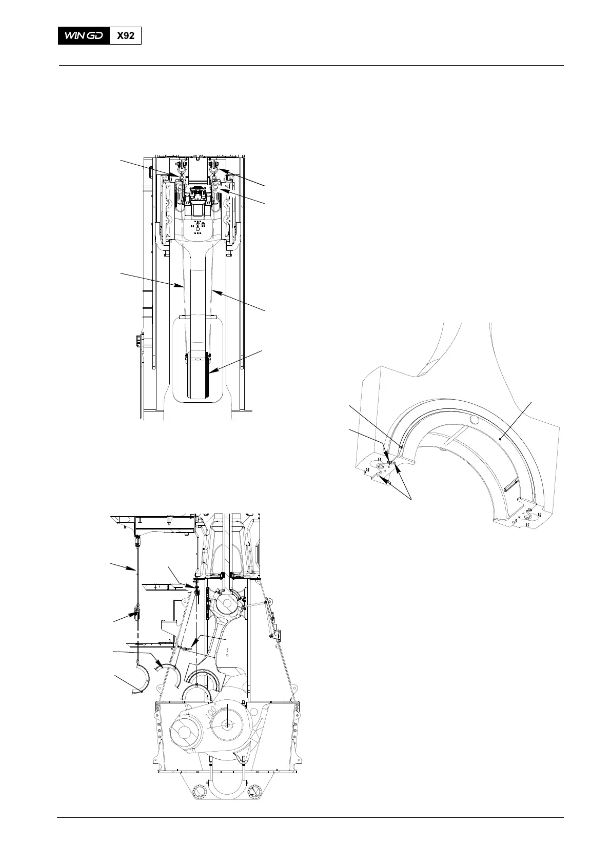
5. Top Bearing Shell −
Removal
1) Attach the manual ratchets 4016−012
(H1, H5, Fig.6) and the shackle
94019P to the column.
2) Attach the console frame 94326 (Fig.7)
to the bearing shell (3) with the four
screws (1).
3) Connect the hooks of the manual
ratchets (H1, H5) to the console frame
94326.
4) Apply a light tension the chains (1,
Fig.6).
5) Remove the two screws (2, Fig.7).
Fig. 7
WCH03013
94326
3
2
1
6) Operate the manual ratchets (H5, H1,
Fig.8) to lower the console frame
94326 together with the bearing
shell (1).
7) Attach the hook of the manual ratchet
(H4) to the eyelet in the console frame
94326.
8) Operate the manual ratchets (H1, H5)
to move the console frame from the
column.
9) Lower the console frame 94326 and
the bearing cover (1) to an applicable
area.
10) Remove the manual ratchets (H1, H5).
11) Remove the console frame 94326.
2015
Bottom End Bearing − Removal, Inspection and Installation
Fig. 6
H1
94019P
H5
94326
WCH03013
1
1
Fig. 8
WCH03013
H4
1
H3
H5/H1
94326
94038−015