Maintenance5552−1/A2
Winterthur Gas & Diesel Ltd.
8/ 9
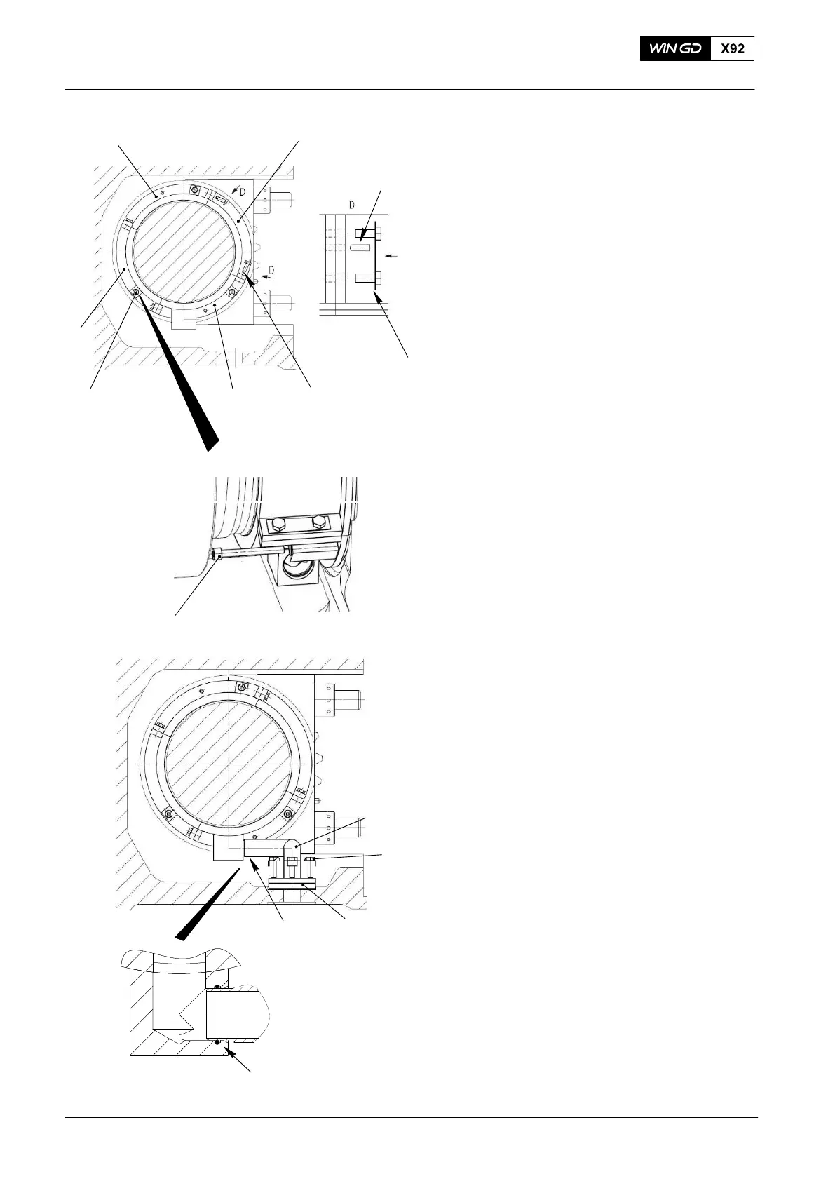
10) Turn the segments (1, 2, 5) clockwise
approximately 90°.
11) Put the segment (6) in position on the
camshaft.
12) Attach the segment (6) to the segments
(1, 5) with the taper pin (3) and the four
screws (4).
13) Torque the eight screws (4) to 20 Nm.
14) Lock the eight screws (4)with the
locking tabs (7).
15) Attach the assembled oil baffle to the
supply unit casing with the three Allen
screws (8).
16) Torque the three Allen screws (8) to
20 Nm.
17) Apply oil to the new O-ring (13).
18) Put the new O-ring (13) in the position
shown.
19) Attach the pipe (9) to the flange (12)
and the oil baffle with the four
screws (10).
20) Torque the the four screws (10) to
20 Nm.
21) Lock the four screws (10) with the
locking tabs (11).
2015
Camshaft and Bearing Shells − Removal and Installation (Independent Lubrication System)
6
3
1
2
4, 7
5
Fig. 8
7
8
8
10
9
11
13 12
13