Maintenance9308−1/A1
Winterthur Gas & Diesel Ltd.
2/ 3
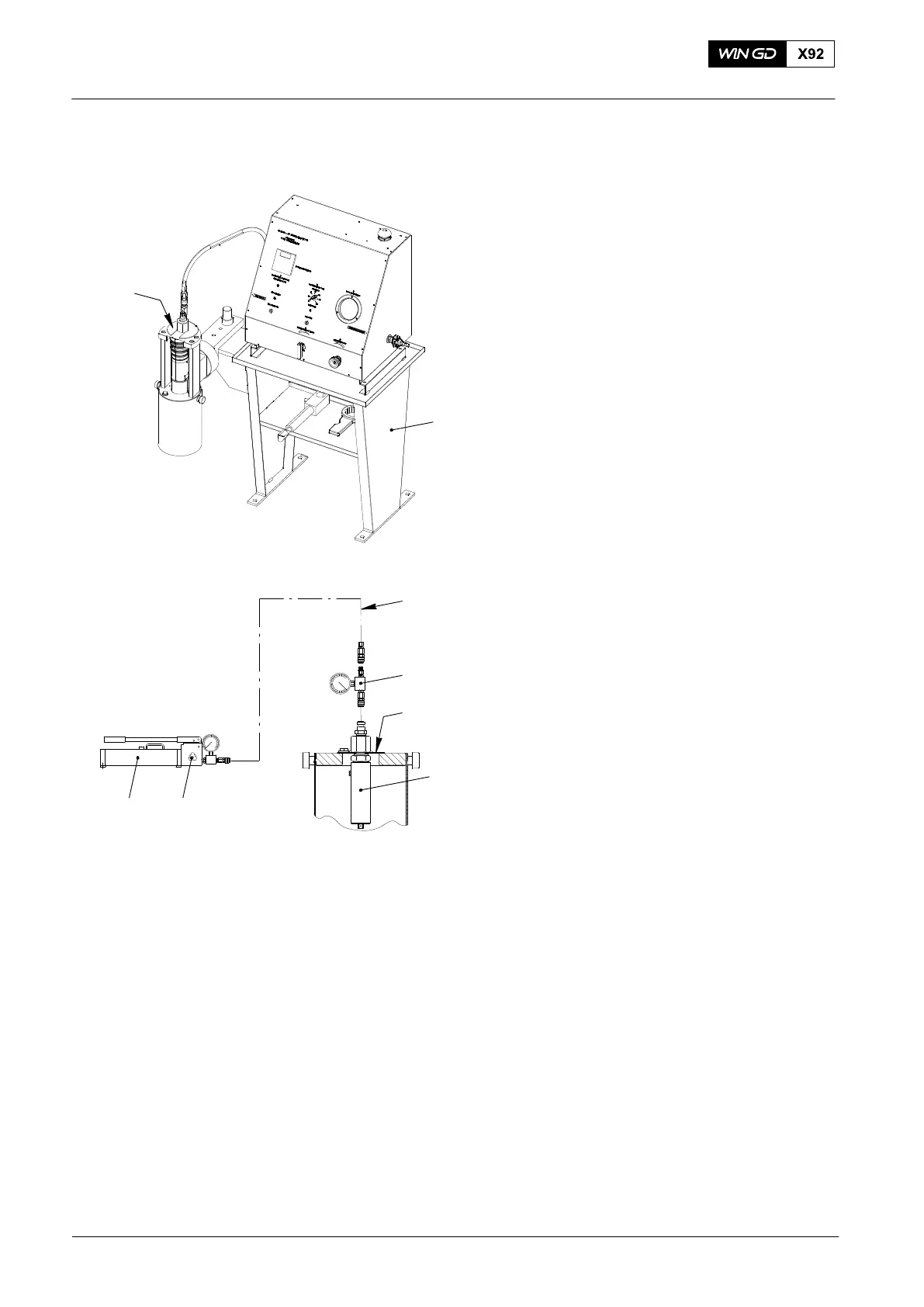
4. Relief Valve Check
There are two alternative procedures to do
a check of the relief valve:
4.1 Procedure One
1) Read the data in the manual for the test
bench (94272).
2) Use the test and calibration fluid, or a
low viscosity oil as a test fluid.
3) Attach the valve holder (94272C), to
the test bench (94272).
4) Attach the relief valve (2) to the valve
holder (94272C).
5) Do a check of the blow-off pressure on
the relief valve (2).
6) Make sure that the relief valve is set to
blow-off at 235 bar. This relates to a
firing pressure of between 166 bar to
169 bar.
7) Release the pressure in the test bench
(94272).
8) Remove the relief valve (2) from the
valve holder (94272C).
4.2 Procedure Two
1) Attach the relief valve (2) to the valve
holder (94272C).
2) Connect the HP oil pump (94931) and
the hose (94935) to the pressure gauge
(94934A).
3) Connect the pressure gauge to the
valve holder (94272C).
4) Close the relief valve (6) on the HP oil
pump.
5) Operate the HP oil pump (94931).
6) Do a check of the blow-off pressure on
the relief valve (2).
7) See next page.
Relief Valve: Blow-off Pressure Check
2015
WCH02260
94272
94935
94934A
94272C
2
WCH02260
94931 6
010.001.02
94272C
Fig. 2