February 2013
4-362
ColorQube® 9303 Family
REP 91.25
Repairs/Adjustments
NOTE: When installing new drum assembly, the three screw holes referenced in Figure 4
are not pre-tapped. There will be resistance when the screws cut new threads. Ensure the
screws are fully seated.
CAUTION
If the marking unit has not been removed. Take care not to contact the printheads with the
drum during the replacement.
Take care not to contact the drum or pinch the encoder wiring when installing the front frame
assembly.
3. Place the drum and front frame assembly in the machine.
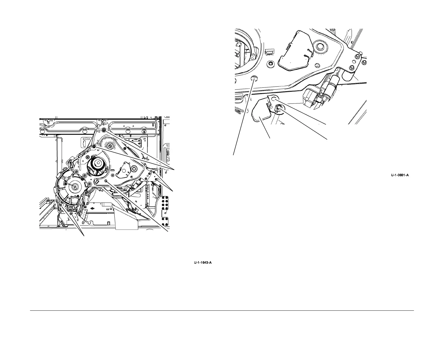
4. Reinstall the screws in the front assembly, Figure 5. Before tightening all the screws,
ensure the pin and bearing are seated correctly, Figure 6. Open and close the stripper
gate, GP 31 checking that the stripper latch mechanism moves freely, Figure 6. If not then
loosen the screws and correct the location of the latching arm before tightening the
screws.
Figure 5 Screw Replacement
Figure 6 Correct seating
5. Remove the drum pulley replacement tool.
6. Replace the drum pulley, REP 91.34.
7. Reinstall the drum drive motor and belt, REP 91.24. Ensure the inner belt surface and
outer pulley surface are thoroughly cleaned before replacement.
8. Reinstall the rear drum thermistor, REP 91.35.
9. Reinstall the stripper blade. Check that the blade cover is sitting in the guide at the rear of
the machine, REP 10.21.
10. Reinstall the drum encoder, REP 91.30.
11. Reinstall the front drum thermistor, REP 91.35.
12. Reinstall the front shroud, PL 94.20 Item 7.
13. Reinstall the front IOD track guide, REP 91.23.
14. Reinstall the IOD assembly, cleaning unit latch handle and abatement plenum, REP
91.22. Check that the harness is connected.
15. Remove the protective drum cover, PL 94.20 Item 13.
16. Connect the harnesses on the front transfix motor, REP 10.4.
17. Reinstall the transfix roll, REP 10.1.
18. Reinstall the transfix blade, REP 10.6.
1
Replace 2 screws (T30).
3
Replace 2 screws.
4
Replace 2 long
screws.
2
Replace screw
2
Pin seated correctly.
1
Bearing seated correctly.
3
Manually rotate the latch
camshaft to verify that the
latching mechanism
slides freely.
4
Install the screw.
 Loading...


