February 2013
4-371
ColorQube® 9303 Family
REP 91.29
Repairs/Adjustments
CAUTION
Do not adjust the ball plate screws (A), Refer to Figure 5.
Figure 5 Ball plate screws
Replacement
1. Replacement is the reverse of the removal procedure.
NOTE: If a type A printhead is being replaced with a type B printhead the following new
cables will also need to be installed:
• Video cable (type B) PL 92.10 Item 7
• Wave amp cable (type B) PL 92.10 Item 8
CAUTION
Failure to do the following may result in printhead or drum damage.
2. Remove the faceplate cover and umbilical port cover from a new printhead.
3. If there is solidified ink on the umbilical nozzles, carefully remove the ink.
4. Gently push in on printhead when starting screws.
5. When screwing the printhead back onto the carriage start by rotating the left screw 2 rev-
olutions, then alternate between the screws doing about 2 revolutions per screw.
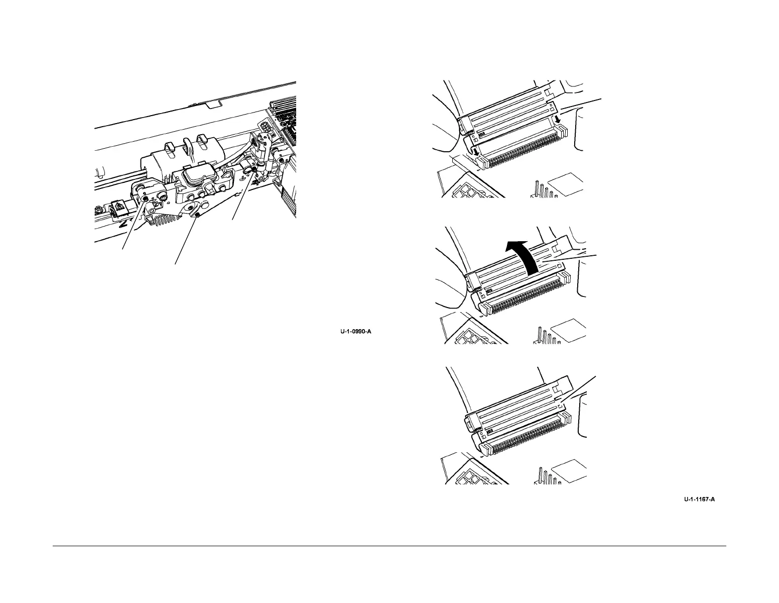
6. Type A printheads only. Connect the flex cables, Figure 6.
Figure 6 Cable connection (type A)
A
A
A
1
Line up the legs behind the
receptacle.
2
Rotate back until the connector
clips into place.
3
Correctly connected flex cable.
 Loading...


