February 2013
4-116
ColorQube® 9303 Family
REP 12.12-110
Repairs/Adjustments
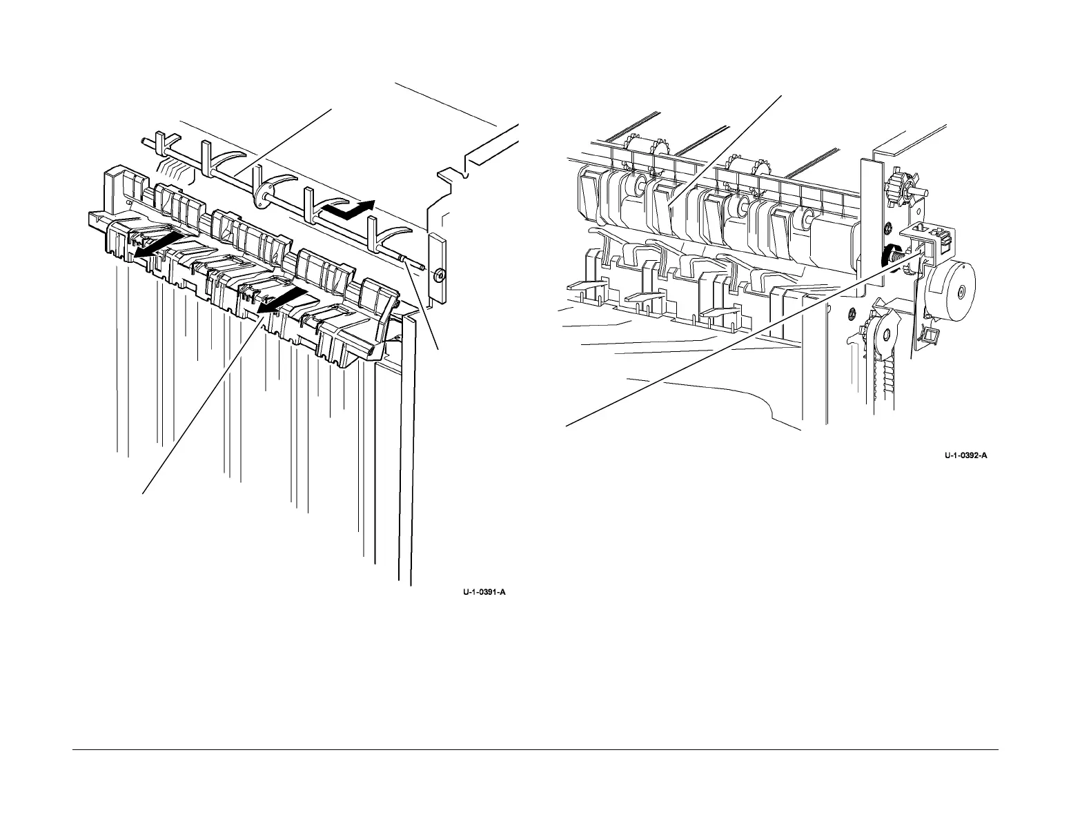
8. Figure 4, remove the paddle wheel shaft assembly.
Figure 4 Paddle wheel shaft removal
Replacement
1. Install the paddle wheel shaft, front bearing and E-clip, refer to Figure 3.
2. Install the output cover, refer to Figure 4.
3. Install the rear bearing and E-clip, refer to Figure 2.
4. Install the gear and flag assembly, refer to Figure 2, ensuring that the gear locates onto
the large “D” flat and the flag locates on the small “D” flat.
5. Install the flag and E-clip, refer to Figure 2.
6. Figure 5, ensure the paddles and flag are correctly aligned.
Figure 5 Paddle alignment
7. Install the motor assembly, refer to Figure 1.
8. Test the operation of the paddle roll, enter dC330, output code 12-238. When the code is
cancelled the paddles must stop with both rubber blades inside of the output cover. If nec
-
essary, check that the gear assembly and flag are correctly located on the “D” flats.
1
Move the output
cover to the right
2
Slide shaft assembly
to the rear
3
Remove the
shaft assembly
Align paddles with the output cover
nsure the encoder flag is within the sensor
 Loading...


