February 2013
4-239
ColorQube® 9303 Family
REP 12.98-171
Repairs/Adjustments
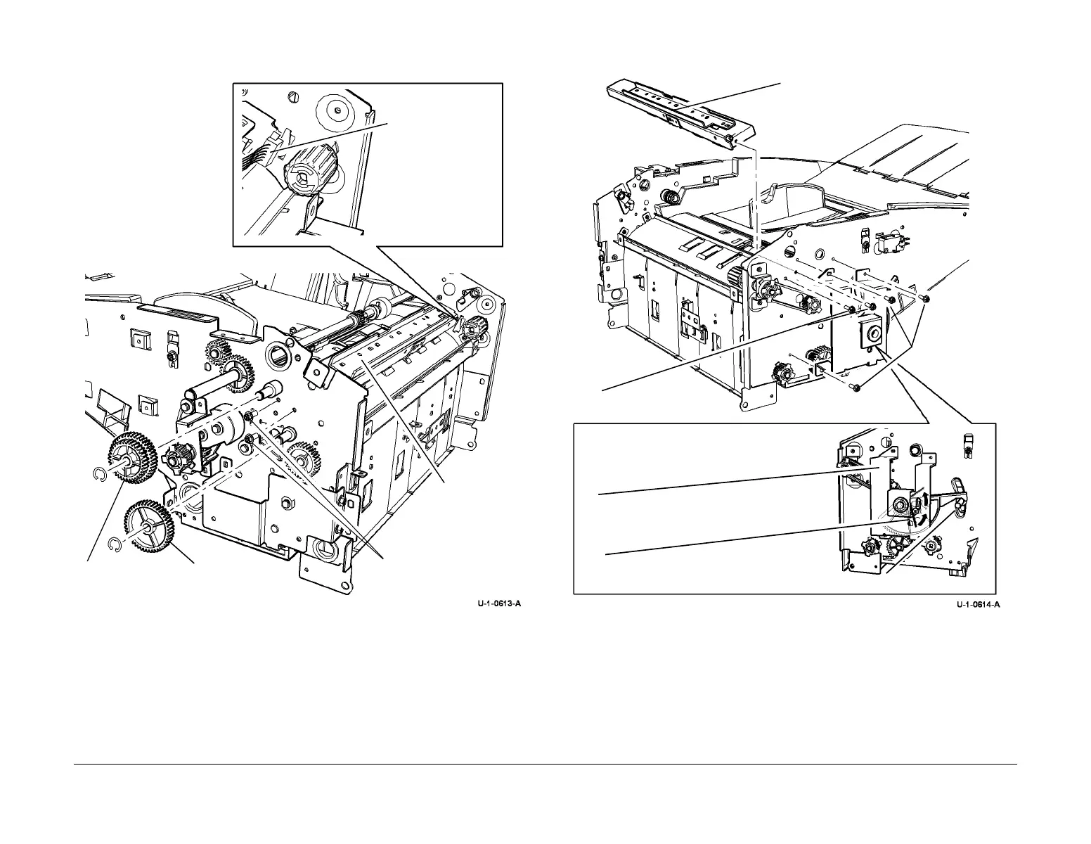
6. Remove the 2 screws at the rear of the idle roller assembly, Figure 1.
Figure 1 Idler Assembly Rear Screws
7. Relieve the torsion spring tension by moving the loading lever and remove 3 of the four
front loading bracket screws. Remove the idle roller assembly, Figure 2.
NOTE: Check that the loading gear remains engaged with the loading shaft gear.
Figure 2 Idle Roller Assembly
Replacement
Reverse the removal procedure to replace the Idle roller assembly.
Replace the loading bracket screws and check that the front loading lever is at the same angle
as the rear loading lever then tension the torsion spring. The loading tray will not operate cor
-
rectly if it is not supported horizontally in the Inserter frame.
3
Remove the clip
and driven gear.
2
Remove the clip
and idler gear.
Idle roller
assembly
1
Disconnect and then
release the harness
from the frame.
4
Remove 2 screws.
4
Remove the idle roller assembly.
2
Remove 3 screws.
3
Turn the loading bracket to access
the 2 screws in step 4.
4
Remove 2 screws.
1
Move the load lever to release the tension
on the torsion spring.
Load Lever
 Loading...


