4-20
Outboard motor troubleshooting
171
172
173
174
Remote control
system (Sub
station [LPS Ir-
regular signal])
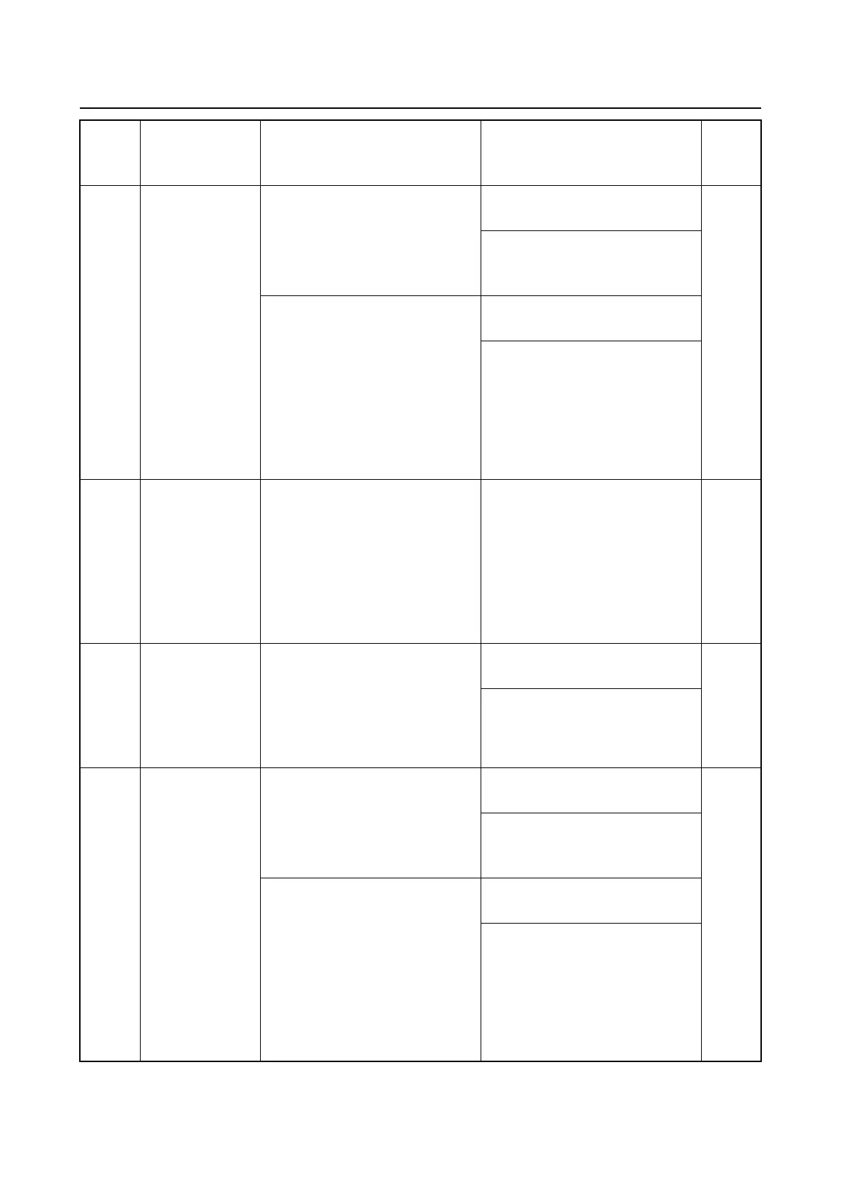
“Check Engine” is displayed.
Locked at engine idle speed.
Alert indicator is ON.
Measure the LPS output volt-
age using the YDIS.
*1
Check for wiring continuity be-
tween the LPS and the Digital
Electronic Control ECM.
Locked at engine idle speed.
Shift actuator rod returns to the
N position.
Alert indicator is ON.
When either one of the trouble
codes 171 and 172, and either
one of the trouble codes 173
and 174 took place simultane-
ously.
Measure the LPS output volt-
age using the YDIS.
Check for wiring continuity be-
tween the LPS and the Digital
Electronic Control ECM.
175
Remote control
system (LPS Ir-
regular signal
[Sub station
Digital Electron-
ic Control ECM
internal circuit
malfunction])
“Check Engine” is displayed.
Locked at engine idle speed.
Shift actuator rod returns to the
N position.
Alert indicator is ON.
Replace the Digital Electronic
Control ECM.
(When replacing the Digital
Electronic Control ECM with a
new one, resetting of Digital
Electronic Control ECM is nec-
essary.)
*1
176
Remote control
system (Sub
station, center
outboard motor
[LPS Irregular
signal])
“Check Engine” is displayed.
Locked at engine idle speed.
Shift actuator rod returns to the
N position.
Alert indicator is ON.
Measure the LPS output volt-
age using the YDIS.
*1
Check for wiring continuity be-
tween the LPS and the Digital
Electronic Control ECM.
177
178
179
180
Remote control
system (Sub
station, center
outboard motor
[LPS Irregular
signal])
“Check Engine” is displayed.
Locked at engine idle speed.
Alert indicator is ON.
Measure the LPS output volt-
age using the YDIS.
*1
Check for wiring continuity be-
tween the LPS and the Digital
Electronic Control ECM.
Locked at engine idle speed.
Shift actuator rod returns to the
N position.
Alert indicator is ON.
When either one of the trouble
codes 177 and 178, and either
one of the trouble codes 179
and 180 took place simultane-
ously.
Measure the LPS output volt-
age using the YDIS.
Check for wiring continuity be-
tween the LPS and the Digital
Electronic Control ECM.
Trou-
ble
code
Item (Condition) Symptom Checking steps
See
page



 To Next Page