5-50
Outboard motor and Digital Electronic Control connection
Outboard motor and Digital Elec-
tronic Control connection
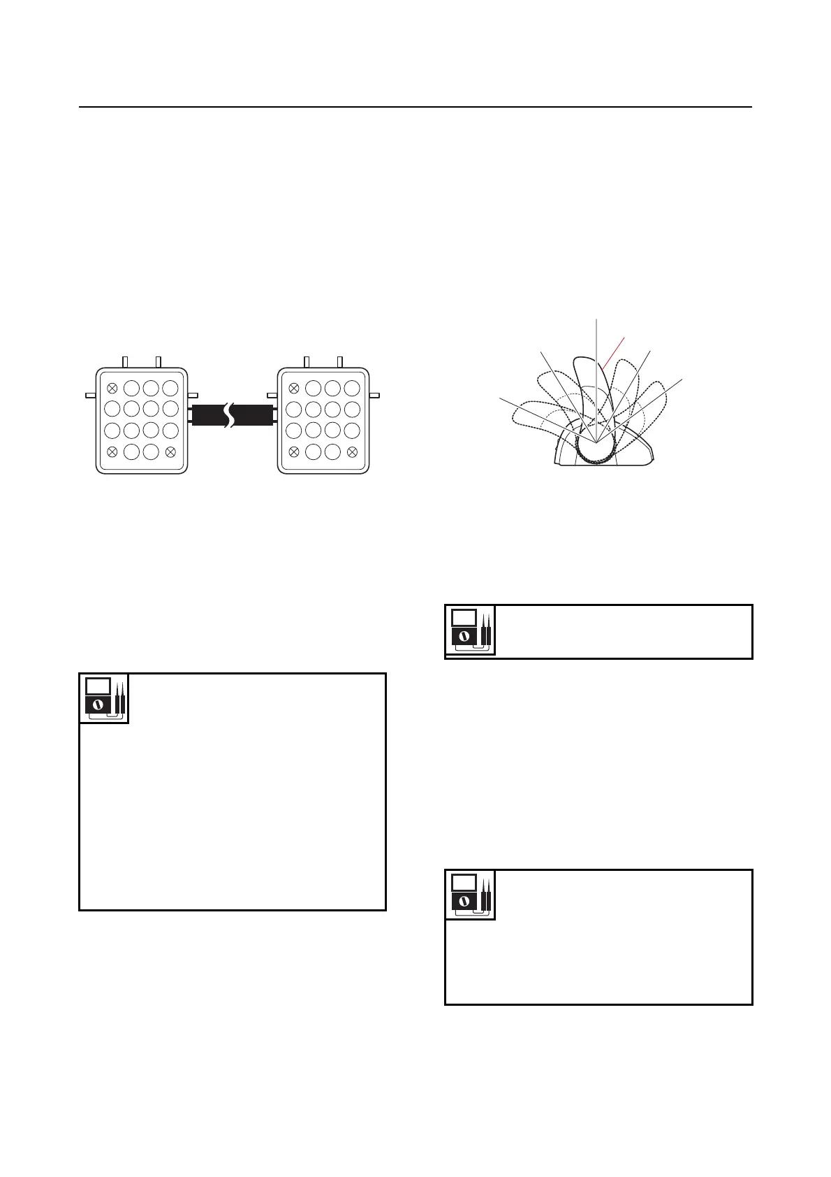
Checking the extension wire harness
1. Check:
• Extension wire harness continuity
Out of specification Replace.
a. Check the extension wire harness for con-
tinuity. Check the wire terminal numbers
from “a” to “m”.
6X9 Digital Electronic Control cir-
cuit
Checking the LPS
1. Measure:
• LPS1 and LPS2 output voltage
Out of specification Check the LPS in-
put voltage.
a. Connect the YDIS to display “LPS 1” and
“LPS 2”.
b. Operate the remote control lever “1”, and
then measure the output voltages of LPS 1
and LPS 2 at the F fully open position “a”,
F shift-in position “b”, N position “c”, R
shift-in position “d” and R fully open posi-
tion “e”.
2. Measure:
• Output voltage difference between LPS1
and LPS2
Out of specification Check the LPS cir-
cuit for continuity.
a. Check the output voltage difference be-
tween LPS 1 and LPS 2.
3. Disconnect:
• Digital Electronic Control coupler “a”
4. Measure:
• LPS input voltage
Out of specification Check the LPS cir-
cuit for continuity.
LPS output voltage:
F fully open position “a”
4.451–4.671 V
F shift-in position “b”
2.659–3.001 V
N position “c”
2.068–2.308 V
R shift-in position “d”
1.467–1.737 V
R fully open position “e”
0.329–0.549 V
a b c
d e f
h
g
i
j
k
l
a b c
d e f
h
g
i j
k
l
m m
LPS output voltage difference
0.1 V or less
Input voltage
5 V
LPS1: Red/White (R/W)–Black/
Red (B/R)
LPS2: Yellow/Red (Y/R)–Green/
Red (G/R)
a
b
e
1
c
d



 To Next Page