5-22
Engine control unit and component
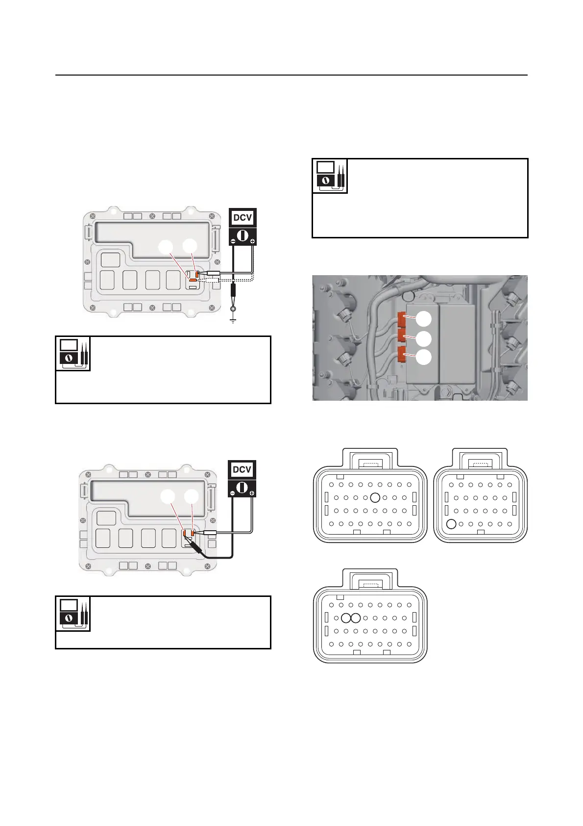
3. Measure:
• Main relay input voltage
Out of specification See “Troubleshoot-
ing procedure (trouble code not detected)”
(4-23).
a. Measure the input voltage between the ter-
minal “a” and ground, and the terminal “b”
and ground.
b. Turn the “POWER” switch to ON, and
measure the input voltage between the ter-
minals “a” and “b”.
c. Turn the “POWER” switch to OFF.
4. Install:
• Main relay
• Relay cover
Checking the engine ECM circuit
1. Check:
• Wire harness continuity
Out of specification Replace the wire
harness.
a. Disconnect the engine ECM couplers “a”,
“b” and “c”.
b. Check the wire harness for continuity.
Input voltage
12 V
Terminal “a”–Ground
Terminal “b”–Ground
Input voltage
12 V
Terminal “a”–Terminal “b”
a
b
Wire harness continuity
Terminal 41–Ground
Terminal 42–Ground
Terminal 86–Ground
Terminal 99–Ground
86
99
4142
a
b
c



 To Next Page