5-36
Charging unit and component
f. While cranking the engine, measure the
peak voltage.
g. Insert the clip into the engine shut-off
switch.
h. Start the engine, and then measure the
peak voltage at the specified engine
speed.
i. Measure the lighting coil output peak volt-
age between all combinations of the con-
nectors.
j. Stop the engine, and then disconnect the
special service tool.
k. Remove the intake manifold (STBD).
l. Connect the lighting coil couplers.
2. Measure:
• Lighting coil resistance
Out of specification Replace.
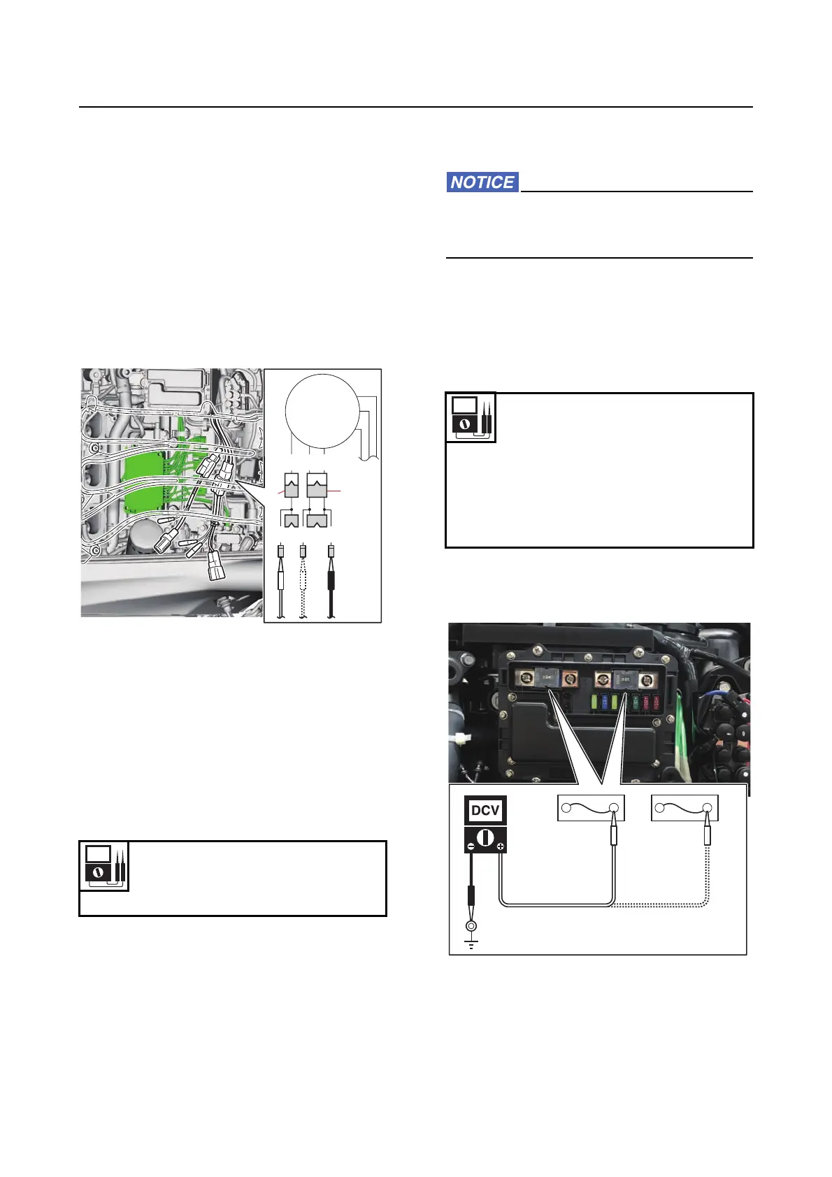
a. Remove the intake manifold (STBD).
b. Disconnect the lighting coil couplers.
c. Measure the lighting coil resistance.
d. Connect the lighting coil couplers.
e. Install the intake manifold (STBD).
Checking the rectifier/regulator/isola-
tor
Do not connect the battery cables in re-
verse. Otherwise, the rectifier/regulator
could be damaged.
1. Measure:
• Rectifier/regulator/isolator output peak
voltage
Out of specification Check the rectifier/
regulator/isolator for continuity.
a. Remove the fuse cover and then measure
the rectifier/regulator/isolator output peak
voltage at the specified engine speed.
2. Check:
• Rectifier/regulator/isolator continuity
Out of specification Replace.
Resistance (reference data)
0.1056–0.1584
Green (G)–Green (G)
BR B
GGG
1
2
Output voltage at 1500 r/min
(loaded) (reference data)
13 V
Output voltage at 3500 r/min
(loaded) (reference data)
13 V
Fuse “a”–Ground



 To Next Page