5-42
Starting unit and component
Starting unit and component
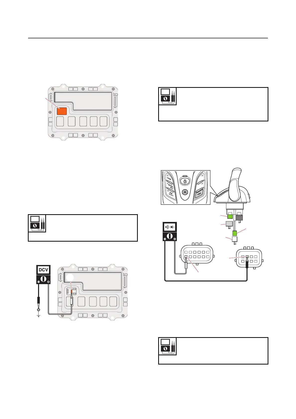
Checking the starter relay
1. Remove:
• Relay cover
• Starter relay “1”
2. Check:
• Starter relay
See step (2) in “Checking the main relay”
(5-21).
3. Measure:
• Starter relay input voltage
Out of specification Check the wire har-
ness for continuity.
a. Measure the input voltage between the ter-
minal “a” and ground.
b. Turn the “POWER” switch to OFF.
4. Install:
• Starter relay
• Relay cover
Checking the power switch
1. Check:
• “POWER” switch continuity (Digital Elec-
tronic Control)
Out of specification Replace the Digital
Electronic Control.
a. Disconnect the Digital Electronic Control
couplers “a” and “b”.
b. Set the digital circuit tester to the diode
mode, and then check the power switch for
continuity.
c. Connect the Digital Electronic Control cou-
plers.
2. Check:
• “POWER” switch continuity (switch panel)
Out of specification Replace.
Input voltage
12 V
Terminal “a”–Ground
1
a
“POWER” switch continuity
Button pushed in:
Tester probe (+) Terminal “e”
Tester probe (–) Terminal “f”
“POWER” switch continuity
Button pushed in:
Terminal “a”–Terminal “b”
a
c
d
c
d
f
e
b



 To Next Page