2-45
Intake and exhaust system
Intake and exhaust system
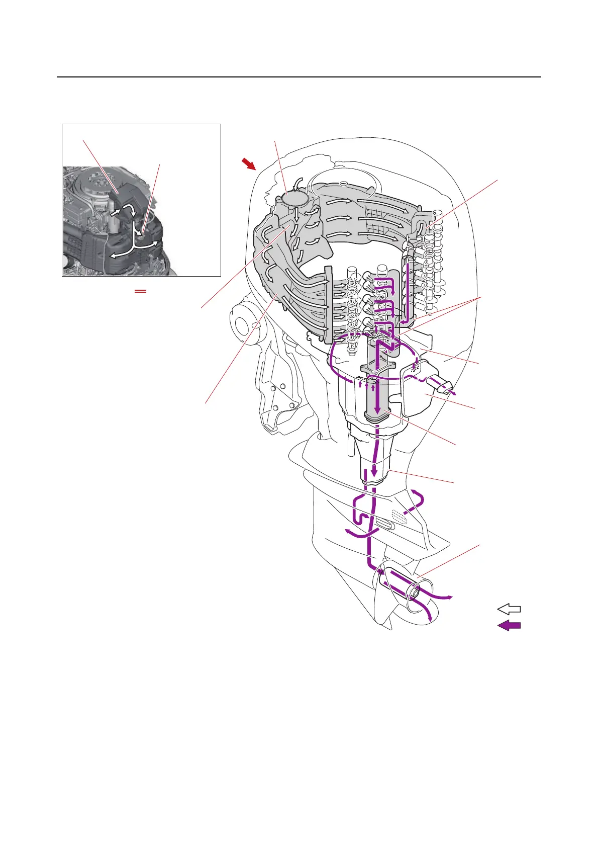
Intake and exhaust diagram
*1. When the remote control lever is in the R
position and the engine speed is 2000 r/min or
less
2. ETV
3. Surge tank
5. Intake manifold
5. Intake
manifold
6. Cylinder
head
7. Exhaust
guide
8. Idle
silencer
9. Exhaust
manifold
10. Muffler
*1
*1
11. Propeller
A
B
C
C
1. Intake silencer
4. Intake air pressure/
temperatur sensor
1. Intake silencer
2. ETV
3. Surge tank
4. Intake air pressure/temperature sensor
5. Intake manifold
6. Cylinder head
7. Exhaust guide
8. Idle silencer
9. Exhaust manifold
10. Muffler
11. Propeller
A. Intake air flow
B. Exhaust gas flow



 To Next Page