5-18
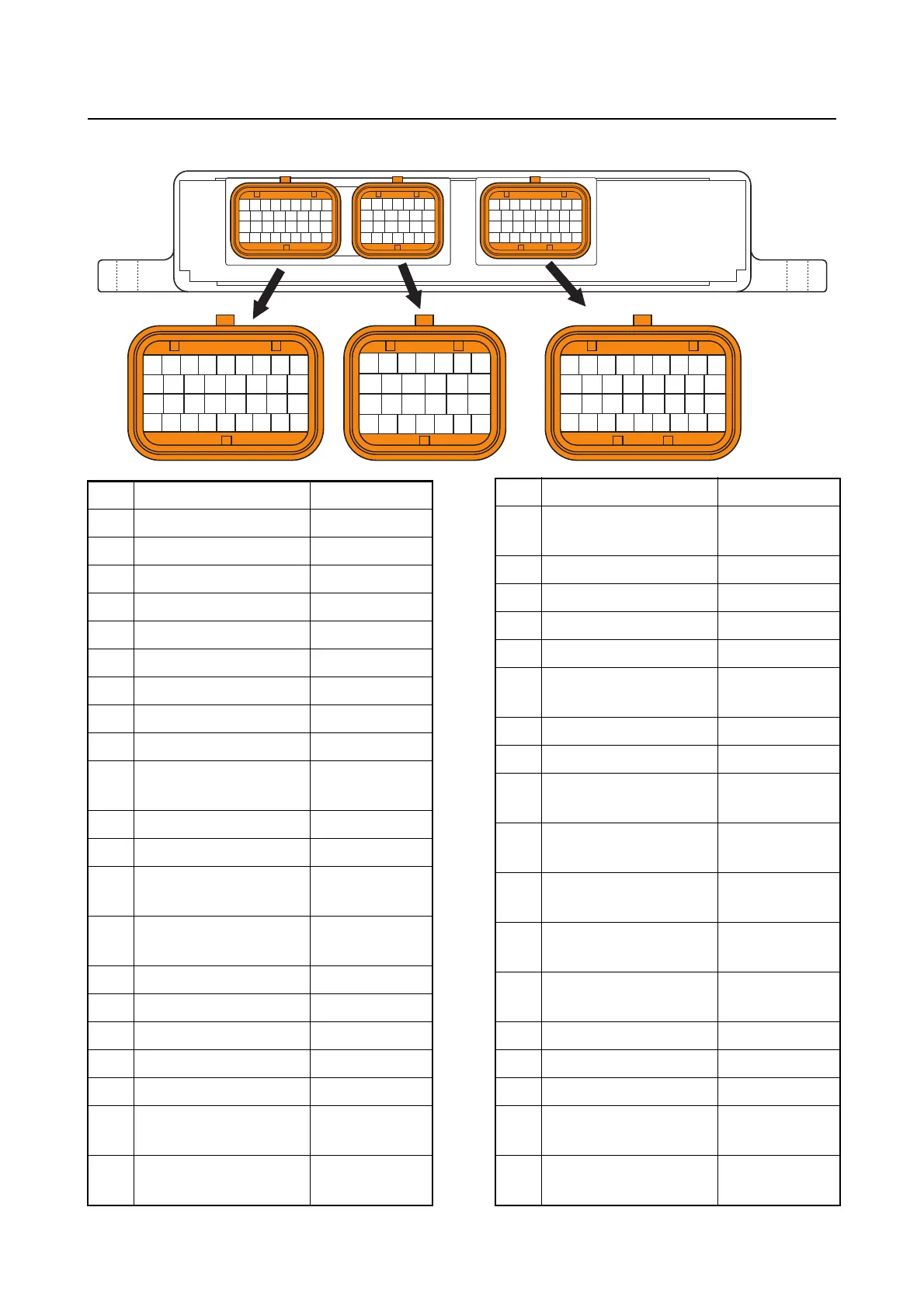
ECM coupler layout
ECM coupler layout
87 88 89 90 91 92 93 94 95
96 97 98 99
61 62 63 64 65 66 67
80 81 82 83 84 85 86
68 69 70 71 72 73
74 75 76 77 78 79
27 28 29 30 31 32 33 34 35
52 53 54 55 56 57 58 59 60
36 37 38 39 40 41 42 43
44 45 46 47 48 49 50 51
100 101 102 103
108 109 110 111104 105
112 113 114 115 116 117 118 119 120
106 107
No. Connecting part Color
27 PTT sensor Pink
28 — —
29 Pulser coil White/Red
30 Shift ground Black
31 Shift ground Black
32 Shift actuator Green/Black
33 — —
34 Shift actuator Green/Red
35 — —
36
Engine shut-off
switch
White
37 Main relay Yellow/Green
38 Engine start switch Brown
39
Cam position sensor
(PORT EX)
White/Blue
40
Cam position sensor
(PORT IN)
White/Green
41 Engine ECM ground Black
42 Engine ECM ground Black
43 Shift power source Red/Green
44 Battery power source Red/Yellow
45 PTT switch (UP) Sky blue
46
Reprogramming con-
nector
Green/Orange
47
Cam position sensor
(STBD IN)
White/Black
48
Water pressure sen-
sor
Blue/Black
49 OCV (STBD) Purple
50 OCV (PORT) Purple
51 Shift power source Red/Green
52 Battery power source Red/Yellow
53
Wake up pulse (Digi-
tal Electronic Control)
Yellow
54 PTT switch (DN) Light green
55 YDIS White/Black
56
High-pressure fuel
pump
Red/Black
57
Thermo sensor
(STBD)
Black/Yellow
58
Low-pressure fuel
pump relay
Yellow/Green
59
High-pressure fuel
pump
Red/Black
60
High-pressure fuel
pump power source
Red
61 ETV power source Yellow/Green
62 TPS 2 Pink/White
63 SPS 2 Pink
64
Engine temperature
sensor
Black/Yellow
65
Intake air tempera-
ture sensor
Black/Yellow
No. Connecting part Color



 To Next Page