7-39
Camshaft
Removing the camshaft, VCT assem-
bly, and driven sprocket
When the timing belt is not installed, do not
turn the crankshaft or camshafts. Other-
wise, the intake and exhaust valves could
collide with each other or with the pistons
and be damaged.
1. Remove:
• Cylinder head cover
See “Camshaft” (7-38).
2. Remove:
• VCT assembly
• Driven sprocket
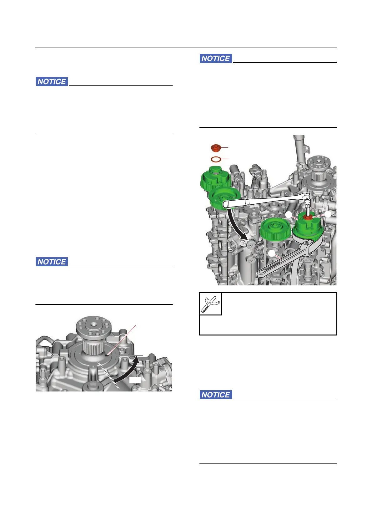
a. Turn the crankshaft counterclockwise 60
gradually until the large “▲” mark “a” on
the crankshaft is aligned with the mating
surface of the crankcase and cylinder
block.
Do not turn the crankshaft clockwise more
than 60. Otherwise, the pistons and valves
could collide with each other and be dam-
aged.
b. Secure the VCT assemblies “1” and “2” us-
ing the special service tool “3”, and then re-
move the VCT caps “4”.
• When removing the VCT cap, do not se-
cure the camshaft. Otherwise, the VCT as-
sembly could be damaged.
• When removing the VCT cap, do not turn
the VCT assembly. Otherwise, the intake
and exhaust valves could collide with
each other and be damaged.
c. Remove the special service tool.
d. Secure the intake camshaft using a
wrench, and then remove the VCT assem-
blies “1” and “2”.
• When removing the VCT bolt, do not se-
cure the VCT assembly. Otherwise, the
VCT assembly could be damaged.
• When removing the VCT assembly, do not
turn the intake camshaft. Otherwise, the
intake and exhaust valves could collide
with each other and be damaged.
Rotor holding tool “3”
90890-04166
Rotor holding tool “3”
YM-04166



 To Next Page