5-51
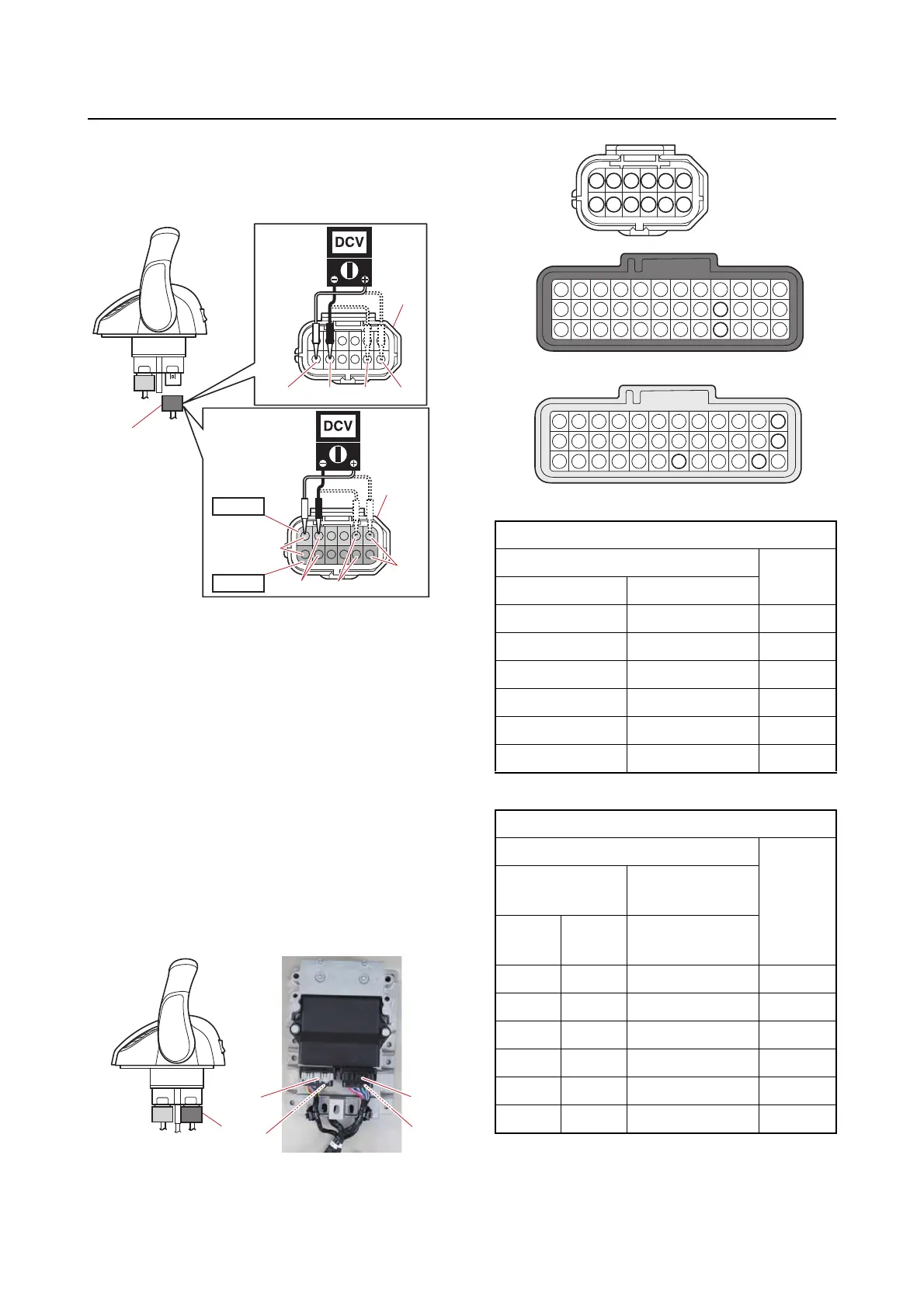
6X9 Digital Electronic Control circuit
a. Turn the “POWER” switch to ON, and then
measure the input voltage at the Digital
Electronic Control coupler terminals (wire
harness end).
b. Turn the “POWER” switch to OFF.
5. Connect:
• Digital Electronic Control coupler
Checking the LPS continuity
1. Disconnect:
• Digital Electronic Control coupler
• Digital Electronic Control ECM coupler
2. Check:
• Wire harness continuity
No continuity Replace the wire harness.
Single lever
Twin lever
3. Connect:
• Digital Electronic Control ECM coupler
• Digital Electronic Control coupler
A. Single type
B. Twin type
R/WB/RG/RY/R
a
a
A
R/W
B/R
G/R
Y/R
a
STBD
PORT
B
LPS circuit continuity
Terminal No.
Color
code
Coupler “a” Coupler “b”, “c”
749Y/R
862G/R
966L/B
10 16 W/L
11 28 B/R
12 37 R/W
LPS circuit continuity
Terminal No.
Color
code
Coupler “a”
STBD: Coupler
“b”, “c”
STBD PORT
PORT: Coupler
“d”, “e”
17 49 Y/R
28 62 G/R
3 9 66 W/B
410 16 W/L
511 28 B/R
612 37 R/W
a
b, d
c, e
7
8 9
10
11
12
1 2 3 4
5
6
16
28
37
49
62
66



 To Next Page